
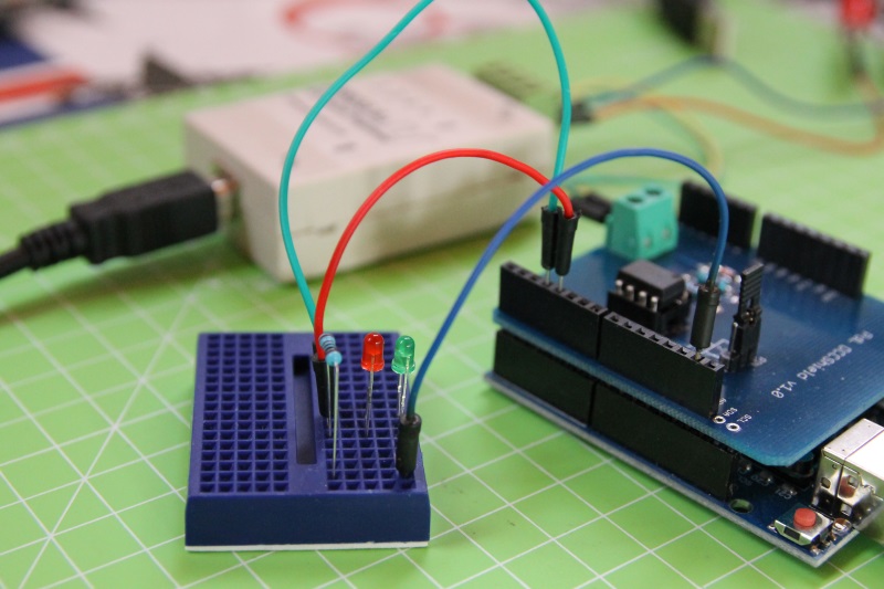
Dopo aver realizzato uno shield per interfacciare Arduino ad un bus DCC, vediamo oggi come realizzare un semplice decoder accessori per controllare dei led.

Decoder accessori
Lo standard DCC (in particolare il documento S-9.2.1 DCC Extended Packet Formats) definisce diversi tipi di decoders, ovvero di dispositivi che – collegati al bus DCC – eseguono operazioni in base ai comandi ricevuti.
Un decoder accessori è “intended for control of a number of simple functions such as switch machine control or turning on and off lights” (pensato per controllare alcune semplici funzioni come scambi o luci).

uno dei decoder DCC autocostruiti di Paco
Indirizzamento
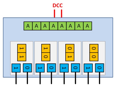
Ogni decoder deve rispondere ad uno o più indirizzi. Il documento S-9.2.1 spiega nel dettaglio la struttura di un pacchetto DCC inviato ad un decoder accessori (basic accessory decoder packet format):
![]()
9 bit del pacchetto (AAAAAAAAA) identificano l’indirizzo del singolo decoder. I bit più significativi (MSB) dell’indirizzo sono quelli nel secondo bytes, mentre quelli meno significativi (LSB) sono quelli nel primo bytes. Per complicare un po’ le cose, i bit del secondo bytes sono in complemento a uno.
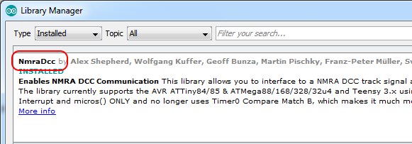
Vediamo un esempio pratico per capire meglio:
![]()
I bit più significativi sono 011. Effettuandone il complemento uno diventano 100.
I bit meno significativi sono 0010011. Concatenando i 9 bit si ottiene 1000010011, il decoder avrà quindi indirizzo 267.
2 bit (PP) indicano l’indirizzo della singola porta del decoder. Per convenzione un decoder accessori ha quindi 4 porte, ognuna formata da una coppia di uscite.
Il bit O indica, per la porta indicata dai bit PP, l’uscita a cui il comando è indirizzato. Infine il bit C indica se l’uscita deve essere attivata (1) o disattivata (0).
Alcuni produttori preferiscono utilizzare un indirizzamento “piatto” (non distinguendo tra indirizzo decoder, numero porta e uscita). Una buona spiegazione di come funzionano le diverse modalità di indirizzamento (MADA, PADA…) è presente sulla wiki di Rocrail.
Arduino
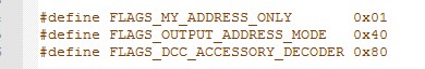
Per sviluppare lo sketch del nostro decoder accessori con Arduino, dobbiamo per prima cosa installare la libreria NmraDcc utilizzando il Library Manager:
Includiamola quindi nello sketch, istanziando anche un oggetto di tipo NmraDcc:
#include "NmraDcc.h" NmraDcc Dcc; |
Nel setup() dobbiamo configurare e inizializzare la libreria. Per prima cosa utilizziamo il metodo pin() per indicare alla libreria il pin di Arduino a cui è collegato il segnale DCC (ExtIntPinNum), il relativo interrupt (ExtIntNum). Decidiamo inoltre se abilitare o meno la resistenza di pullup interna:
void pin(uint8_t ExtIntNum, uint8_t ExtIntPinNum, uint8_t EnablePullup); |
L’elenco dei pin utilizzabili per ogni board Arduino è disponibile nella wiki, mentre si può utilizzare il metodo digitalPinToInterrupt() per ottenere il numero di interrupt associato ad un determinato pin.
Se state utilizzando lo shield che ho presentato in un precedente articolo con una scheda Arduino Uno, il pin da configurare è il numero 2 con resistenza di pullup attiva, quindi:
#define DCC_PIN 2 [...] Dcc.pin(digitalPinToInterrupt(DCC_PIN), DCC_PIN, 1); |
Passiamo ora alla configurazione della libreria, con il metodo:
void init(uint8_t ManufacturerId, uint8_t VersionId, uint8_t Flags, uint8_t OpsModeAddressBaseCV); |
I primi due valori indicano il codice produttore e la versione del decoder e possono essere ottenuti dalla centrale DCC leggendo le relative CV (configuration variables). Per i decoder autocostruiti, il ManufacturedId viene impostato a MAN_ID_DIY.
Il terzo valore consente di indicare, in OR, alcuni flags:
Per un decoder accessori dobbiamo utilizzare il terzo flag (DCC_ACCESSORY_DECODER).

Terminata la configurazione della libreria, perché questa gestisca i messaggi DCC in ingresso dobbiamo chiamare, all’interno del loop(), il metodo process() quanto più frequentemente possibile:
void loop() { Dcc.process(); } |
Alla ricezione di un messaggio diretto ad un decoder accessori, la libreria può chiamare diversi metodi, in base a quanto definito all’interno dello sketch:
- notifyDccAccState()
- notifyDccAccTurnoutBoard()
- notifyDccAccTurnoutOutput()
- notifyDccSigState()
I primi 3 metodi sono invocati per messaggi di tipo basic accessory decoder packet, mentre l’ultimo per extended accessory decoder control packet.
Per il decoder che stiamo realizzando ho scelto il metodo notifyDccAccState():
void notifyDccAccState(uint16_t Addr, uint16_t BoardAddr, uint8_t OutputAddr, uint8_t State) |
Questo metodo mette a disposizione alcuni parametri. Vediamo il loro significato tenendo presente quanto spiegato ad inizio articolo sull’indirizzamento:
- BoardAddr è l’indirizzo (9 bit) del decoder
- OutputAddr rappresenta i 3 bit PP e O, ovvero l’indirizzo della porta e dell’uscita
- State è il comando (1 = attivazione, 0 = disattivazione)
- Addr è indirizzo diretto della porta (modalità PADA)
Possiamo separare l’indirizzo della porta (2 bit) da quello della relativa uscita (1 bit) con:
int portAddress = (OutputAddr >> 1) + 1; int outAddress = OutputAddr & 0x01; |
Ho aggiunto 1 all’indirizzo della porta per identificare le porte del decoder con indirizzi da 1 a 4 invece che da 0 a 3.
Il decoder di questo articolo avrà definito come costante nello sketch sia l’indirizzo della scheda, sia quello della porta (in un prossimo articolo vi mostrerò come renderli dinamici):
#define BOARD_ADDRESS 5 #define PORT_ADDRESS 1 |
Possiamo quindi verificare che il comando sia indirizzato al nostro decoder con:
if((BoardAddr == BOARD_ADDRESS) && (portAddress == PORT_ADDRESS)) { |
e modificare lo stato di due pin digitali (a cui ho collegato due led) in base all’indirizzo dell’uscita e al comando:
if(outAddress == 0) { digitalWrite(RED_LED_PIN, HIGH); digitalWrite(GREEN_LED_PIN, LOW); Serial.println("! RED led activated"); } else { digitalWrite(RED_LED_PIN, LOW); digitalWrite(GREEN_LED_PIN, HIGH); Serial.println("! GREEN led activated"); } |
Il codice sorgente del decoder è disponibile sul mio repository Github; ecco un filmato che ne mostra il funzionamento (sottotitoli in italiano disponibili):


Hello ,Saw you video in You tube great job.
Do you know how to accomplish this without DCC shield that you are using
more I was looking for a bread board example using Uno
Thanks
Hi, you only need to add to your breadboard the same “dcc interface” I’m using in my shield…
Congratulations Luca, you did a really good tutorial.
I’m developing a board to create a decoder for signals. this is composed of an AtMega328 chip, 2 ULN2803 to have an amplified output, with in addition a 5v and 12v power supply and the input for DCC with an optocoupler.
At the moment I program it via serial but I would like to know more about CV so I don’t depend on serial anymore and configure the different aspects of the signals via CV as the QDecoder product does more or less.
I am waiting for more tutorials on DCC topic
Thanks Marcello
Thanks Marcello, I’m working on a series of tutorials about DCC and Arduino… stay tuned 🙂
Hello.
I am from Poland and I found your website. I don’t speak English, I use google translator
I have a question. I made a decoder based on arduino nano. When I send 1AAACDDD instruction to it, the decoder only receives when CDDD = 0010 or 1010 or 0110 or 1110 why?
It does not receive for addr = 1 and 3
Hi Marek. Not sure to have understood your question: are you using the NmraDcc library? The “AAA” bits are the most-significant bits (1-complement) of the address (see S-9.2.1) and the library takes care of “merging” them to the remaining bits to give you the full address in the callback method.
I did not expect you to answer so quickly – thank you. Yes I using NmraDcc. CDDD is your CPPO. I send to the decoder from my arduino Mega and my program. Preanble 16 bits “1” then Pacet start bit “0” then the low byte of the address 1AAAAAAA then bit 0 and then 1AAACDDD (your CPPO) then Pacet start bit “0” then Error detection data then Packet END bit “1”. As in s-9.2.1
I send 10AAAAAA = 10000000 DEC=129, 1AAACDDD(CPPO)=11110010 and the decoder receives Addr = 2 (second pair), Outpower = 0 (becouse C=0), Direction = 0(information that the decoder controls the first output of the pair), and that’s ok,
wen I send 10AAAAAA = 10000000 , 1AAACDDD=11111111 the decoder is not picking, and it should be Addr =4 (fourth pair), Outpower =1 (becouse C=1), Direction = 1(information that the decoder controls the second output of the pair. Unless I get it wrong
The decoder only understands what comes to it when CDDD = 0010 or 1010 or 0110 or 1110
Quite strange… I gave a look at the Library source code and there’s nothing that prevents from receiving CDDD = 1111. Did you set the FLAGS_OUTPUT_ADDRESS_MODE flag (to use the notifyDccAccTurnoutOutput() callback)? If so direction is bit D0, OutputPower is bit C and OutputAddress is made by A bits and D1D2 bits. The only thing is that the library substract 1 when calculating the outputAdress:
OutputAddress = (((BoardAddress - 1) << 2 ) | TurnoutPairIndex) + 1 ;Maybe you can try to use the alternative callback method (notifyDccAccTurnoutBoard) that gives you separate parameters (
notifyDccAccTurnoutBoard( BoardAddress, TurnoutPairIndex, direction, outputPower );) to see what’s happening under the hood…I send 10AAAAAA = 10000001 DEC=129 sorry
For three days I thought if I understood everything correctly. Turns out the bug was in sending commands in my base program. But I found hooray. I’m sorry everything is ok. By the way, you are doing a very good job and have the gift of translation. I will be waiting for your next articles. Good luck. Now I am working on a train signal decoder