

Today I worked on a prototype to understand how to use an Arduino to “control” a nixie tube. The goal was to write a sketch to display a sequence of digits from 0 to 9.
Schematics
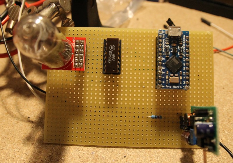
First, let’s analyze the schematics of my prototype:

As I explained in the previous post, a nixie tube has one terminal (anode) that must be connected, through a 10Kohm resistor, to the high voltage (about 170V). The remaining terminals (cathods) are connected to the corresponding PINs of the 74141 IC (or it’s russian version, K155ID1). This is a BCD to decimal driver: it reads the BCD (binary-coded decimal) value on the 4 input PINs (A-B-C-D) and enables the corresponding output.
The IC’s datasheet includes its truths table, that is the list of different input values and the corresponding output:

For example, if the input state is (D,C,B,A) = (0,0,1,1) the active output is number 3 and therefore 3 is the digit the tube displays.
I chose an Arduino Pro Micro and connected its PINs 2,3,4,5 to the driver‘s PINs A,B,C,D. Then I connected power (5V) and ground of Arduino and driver to the low voltage output of the power supply module.
Sketch
The sketch (available on my Github repository), first defines the truths value above as a matrix:
byte bcd[10][4] = { {0,0,0,0}, // 0 {0,0,0,1}, // 1 {0,0,1,0}, // 2 {0,0,1,1}, // 3 {0,1,0,0}, // 4 {0,1,0,1}, // 5 {0,1,1,0}, // 6 {0,1,1,1}, // 7 {1,0,0,0}, // 8 {1,0,0,1}, // 9 }; |
Within the setup(), I configure all the 4 PINs connected to the driver as output:
for(int i = 0; i < 4; i++) pinMode(nixiePins[i], OUTPUT); |
while in the loop() I simply loop between the values 0…9, enter the corresponding position of the matrix and send to the output PINs the BCD value I read from it:
for(int j = 0; j < 10; j++) { for(int i = 0; i < 4; i++) digitalWrite(nixiePins[i], bcd[j][i]); delay(500); } |
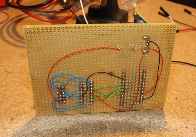
Prototype
The prototype is built on a perfboard and all the connections are created using kynar wire:


Demo
Here’s a small video about the prototype in operation:


