
In addition to the love for electronics, in my (little) spare time I’m working with my friend Davide on a model railway in H0 scale; in particular my main task is to take care of the digital control of locos, turnouts and accessories.

The de facto standard to digitally control a model railway is named DCC (Digital Command Control); it is a communication protocol defined by the american National Model Railroad Association. The specs of the protocol are available on NMRA’s website.
Using DCC, you control a loco sending commands through the rails to modules (decoders) installed within the loco itself: based on the commands it receives, the decoder controls motor, lights and in some cases also sounds and smoke generators…
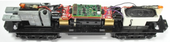
DCC decoder installed in a locomotive
Specific decoders are also available to control turnouts and accessories:

turnout DCC decoder DCC by Esu
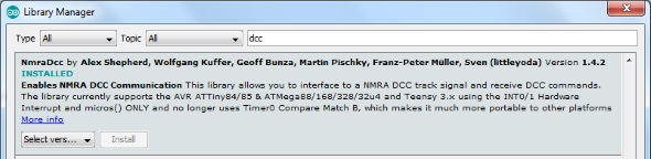
Thanks to Alex Shepherd and other developers, an Arduino library is available to receive and parse DCC commands.
You can install the library using the IDE’s Library Manager:
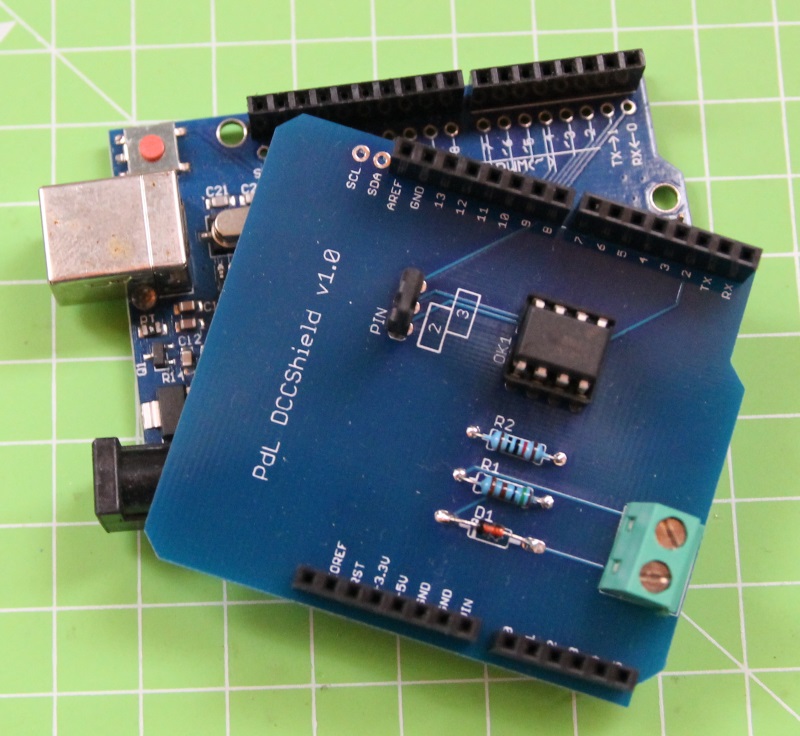
I designed in Eagle a simple shield to have an optocoupled connection between Arduino and the DCC bus:

The NmraDcc library requires that you connect the DCC signal to an Arduino pin which supports interrupts. Because of Arduino Uno has pin 2 and 3 with that feature, I added a jumper to the shield you can use to choose the pin:

The Eagle files for the shield are available on Github; in the same repository you can also find an example program, which changes color and brightness of an led based on speed and direction of the loco with id 10:
The use of the library is quite straightforward. First specify the pin for the DCC signal:
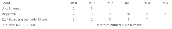
Dcc.pin(0, 2, 1); |
The first parameter is the interrupt number, the second is the pin number and the third is the status of the internal pullup resistor (1 means enabled). You can find the link between pin and interrupt number in the official documentation:
Then initialize the library:
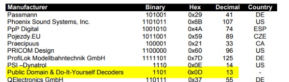
Dcc.init(MAN_ID_DIY, 10, 0, 0); |
The first two parameters are the manufacturer and the version of the decoder. NMRA keeps a list of manufacturers and reserved the value 0x0D (constant MAN_ID_DIY) for opensource and DIY decoders:
With the third parameter you can change the default behaviour of the library:
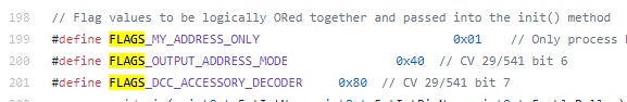
while the last one is the EEPROM address from which the library stores its values.
To let the library process incoming packets, you have to call the process() method as frequently as possible in the loop:
Dcc.process(); |
If the library receives a command to change the speed/direction of a loco, it executes the callback function notifyDccSpeed:
void notifyDccSpeed( uint16_t Addr, DCC_ADDR_TYPE AddrType, uint8_t Speed, DCC_DIRECTION Dir, DCC_SPEED_STEPS SpeedSteps ) { |
in this function I implemented the code that controls the led.


Conosci ?
http://www.dccinterface.com/
Ciao Luca, mi piacerebbe far azionare i servo da programmi quali RocRail o TrainController i quali gestiscono i protocolli di molte centrali digitali. Per fissare le idee ti chiedo se può essere possibile che dallo schema del tracciato visualizzato dal software tipo TrainController (o RocRail), modificando lo stato di un deviatoio col classico click del mouse, questo comando possa essere trasmesso, per mezzo della tua interfaccia qupresentata, ad Arduino e quindi alla scheda scheda 16-Channel 12 bit PWM Servo che azionerà il servo. Sono già in possesso dei seguenti sistemi DCC : Lenz LZV100+LI101F e Digitrax DCS 100 + PR3. Sono settimane che cerco di dare una risposta a questo quesito e mi pare di essere arrivato a bussare alla porta giusta per avere una risposta definitiva. Grazie in anticipo se avrai il tempo di rispondermi.
Nel caso di risposta affermativa, come posso reperire la shield già montata od in kit e con quali protocolli funziona?
ciao Gianni. Si, ti confermo che quello che vuoi fare è proprio realizzare un “decoder accessori” che, rispondendo ai comandi DCC ricevuti dalla centrale (eventualmente “prodotti” da un software quale TC o Rocrail), esegua azioni quali muovere un servocomando. Non ho in vendita lo shield ma ho qualche avanzo del primo batch quindi posso mandarti il PCB… contattami dal sito!
these guys sell them either as a board, a kit or fully assembled
https://www.dccinterface.com/product/arduino-uno-model-railway-dcc-interface-shield/
thanks, they don’t publish the schematics but from the photos it seems very similar to my design
Ma poi lo shield va collegato al booster?
ciao riccardo, lo shield funziona come un “dispositivo” DCC, quindi va collegato al segnale DCC. Questo può provenire da un booster, direttamente dalla centrale, preso dalle rotaie… dipende dal layout del tuo plastico.
Ciao Luca,
complimenti per il bel lavoro.
Vorrei sapere se hai portato ancora avanti il progetto.
Mi piacerebbe capire se pensi sia possibile creare una specie di dialogo bidirezionale per sapere dove è il convoglio.
grazie
Andrea
ciao Andrea, lo shield funziona e l’ho utilizzato in diversi altri progetti. Sto per pubblicare la versione nuova che consente anche di leggere le CV. Per conoscere la posizione dei treni, normalmente si utilizzando sensori di “feedback” appositi su un bus diverso (S88, XpressNet, Loconet…) a seconda poi della centralina/software che vuoi utilizzare. Esiste effettivamente anche il DCC “bidirezionale” ma richiede l’utilizzo di booster e centraline appositi.
Ciao Luca,
Complimenti per lavoro e descrizione.
E’ possibile acquistare il PCB?
Ciao
Fiorenzo
Ciao Fiorenzo, ti scrivo via mail…
Ciao Luca, avrei la stessa richiesta di Fiorenzo.
Mi sai dire qualcosa?
Grazie
Eugenio
Olá Luca.
Eu montei um DCC Booster e não estou conseguindo instalar o programa do Arduino. Onde obtenho o “BoosterBoard.h” ?
Hi Jose, all the files are in my Github repository
Olá Luca.
Todos os arquivos que eu instalei do seu repositório Github estão dando erro. Qual a razão disto acontecer ?
Jose, it’s quite hard to guess your problem without additional details: which file, which error… If you prefer, open an issue on Github to track the problem