
Some time ago my friend Mauro Alfieri showed me an interesting development board produced by DFRobot and called Bluno Beetle (now Beetle Ble). It seemed the perfect board to start “playing” with the Bluetooth Low Energy (BLE) technology; therefore I ordered one board directly from the DFRobot store.
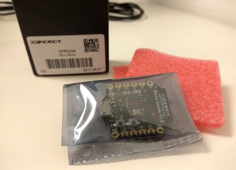
I expected to receive the usual anonymous parcel with the board inside an antistatic plastic bag; DFRobot instead sends its products in an elegant cardboard box, protecting them with foam:
Bluno Beetle is really small and therefore perfect for wearable projects:
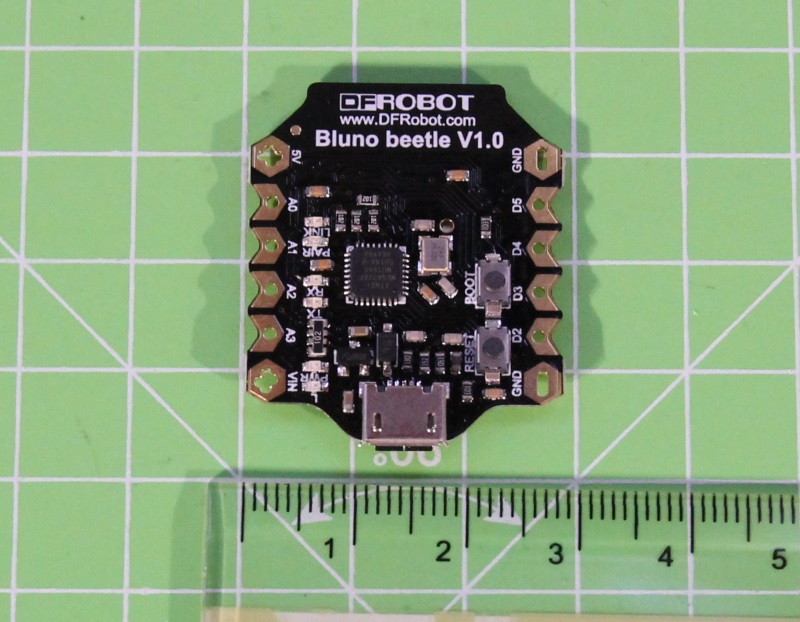
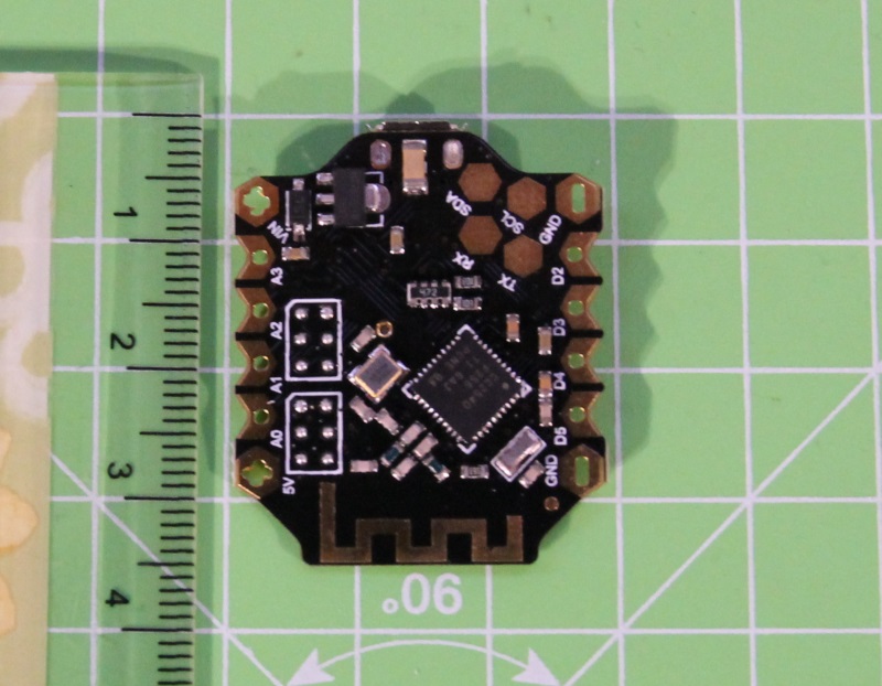
But what is it? Simplifying is a board, Arduino Uno compatible (it hosts the ATmega328P microcontroller) to which has been added the CC2540 chip from Texas Instruments to act as USB and BLE controller. The two chips communicate via a serial interface:

The CC2540 chip is actually a real microcontroller that runs a firmware developed by DFRobot. This firmware can be configured using AT commands. Normally the firmware runs in transparent mode, that is it acts as a “bridge” between the USB/BLE interfaces and the ATmega microcontroller. If you then connect the Bluno to your PC and activate the serial monitor, each character you type is forwarded to the ATmega and viceversa.
To send AT commands, first you have to enter the AT mode of the firmware, sending the + character 3 times (without appending a line ending). The firmware confirms the new mode with the sentence “Enter AT Mode”:

Now you can send the commands, appending the Windows line terminator (CRLF). For example to display the firmware version:

To exit the AT mode and go back to transparent mode, you have to send the AT+EXIT command.
Drivers
It may happen that – if it’s the first time you connect the Bluno Beetle to your Windows PC – it is not correctly recognized:

The correct drivers are shipped with the Arduino IDE. You only need to do a manual installation specifying the path where you installed the IDE:

Windows will identify the new device as an Arduino Uno:

Arduino
As explained above, if the firmware running on the CC2540 chip is in transparent mode, using the USB connection you can talk directly to the ATmega328P microcontroller. This means that you can program the microcontroller using the Arduino IDE without any problems… just choose Arduino Uno as board and select the correct serial port:

BLE and transparent mode
In transparent mode Bluno transmits via BLE each byte it receives from Arduino (the ATmega microcontroller) and – viceversa – it sends to Arduino each byte it receives from BLE.
In this first post let’s explore the demo application DFRobot provides; in a future post I’ll explain how to develop your application to interact with Bluno Beetle via BLE.
If you have an Android smartphone, you can directly install the apk file for the application named BlunoBasicDemo (application of which the source code is also available). In the same Github repository you can also find the source code of the iOS application, you have to compile by yourself.
Compile and upload the following sketch on the board:
unsigned long previous_time = 0; void setup() { Serial.begin(115200); } void loop() { if (Serial.available() > 0) { int incomingByte = Serial.read(); Serial.print("New byte received: 0x"); Serial.println(incomingByte, HEX); } unsigned long actual_time = millis(); if(actual_time - previous_time > 10000) { Serial.println("Hello world!"); previous_time = actual_time; } } |
The sketch reads the incoming bytes (coming from the app) and sends back to the app their hexadecimal value. Every 10 seconds moreover the sketch sends to the app the text Hello world!.
Launch the app. After having clicked on the Scan button, you can choose your Bluno board from the list of detected devices:

Every 10 seconds you should see a new HelloWorld! string appear. You can try to send a character (for example the letter “a”); you’ll receive an answer from Arduino (0x61 is indeed the hex code – in the ASCII table – for the letter “a”):

HID mode
Bluno also supports the HID (Human Interface Device) mode. When running in this mode, Bluno simulates an input peripheral (keyboard, mouse…) connected via BLE.
The AT command that enables this mode is:
[checklist]
- AT+FSM=FSM_HID_USB_COM_BLE_AT
[/checklist]
After having enabled the HID mode, you can send one or more “keys” with:
[checklist]
- AT+KEY=
[/checklist]
you can send up to 3 different keys at a time, concatenating their codes with the + character. The codes to be used, according to the type (page) of the HID device, are listed in the USB specification.

Debug mode
Using two different AT commands you can enable the debug mode of the firmware. This mode allows to receive – via the USB connection – a copy of all the data sent and received through the BLE connection.
The two commands are:
[checklist]
- AT+BLUNODEBUG=ON (copies the messages sent by the ATmega)
- AT+USBDEBUG=ON (copies the messages received from BLE)
[/checklist]

By default the first debug mode is active, while the second is disabled. You can verify it if you upload the sketch listed above: in the serial monitor you’ll see the Hello World! sentences but not the characters sent by the app.


Did you give up on this little board and just end up using it as sensor readout over ble? xD