
I’m working with Eagle to prepare a PCB for a Nixie clock. I wasn’t able to find a library for the Nixie I chose so I had to create it from scratch.
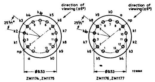
Nixie’s datasheet has the following drawing about pins disposition:
Let’s see how to draw it in Eagle, thanks to an ULP (User Language Program).
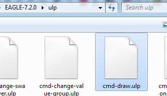
Choose File – Run ULP…

Click on cmd-draw.ulp:
Choose Pad, then enter the values for the radius (0.19 mils) and the angle between two pads (25.714°) as explained in the datasheet. You can also define shape and size for the pads:

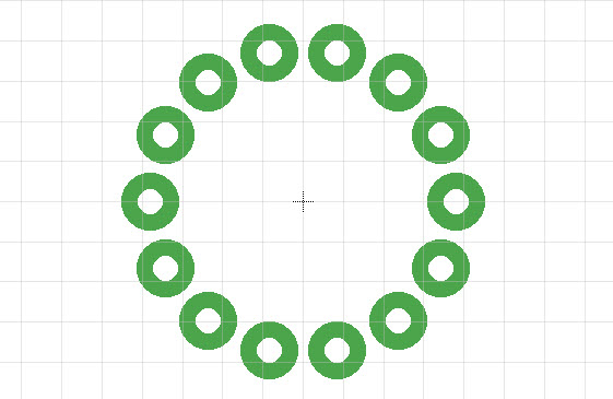
Click on OK and confirm the generated script with OK again:

The result:


Hi, i try in verson 8.6.0 and i missing “Pad” i have only Hole and Via 🙁
Mark