
You probably already know the esp8266wifi chip, made by Espressif. It appeared on some Chinese webstores in the middle of 2014 and in the beginning it was used as a “bridge” to connect microcontrollers (Arduino…) to wifi networks thanks to its very low cost (about 5$ for a module).

Because of the original firmware was not well documented, it has some bugs and offered only “standard” features (via AT commands), the maker community developed some alternative firmwares (the most famous of which is surely NodeMCU), to fully exploit the chip power and to build complete systems, without the need of external microcontrollers:

ESPToy, by Rayshobby
In September 2016, after a beta testing phase lasted some months, Espressif announced and made available the successor of esp8266, named ESP32.
The main features of the new chip are the following:
[checklist]
- Tensilica LX6 dual core processor at 240 MHz
- 520Kb of SRAM memory
- Wifi 802.11 b/g/n connectivity with support for WEP, WPA/WPA2 PSK/Enterprise
- Bluetooth connectivity (classic and LE)
- 32 I/O pins with several builtin peripherals
- hardware acceleration for security algorithms (AES, SHA2, RSA-4096)
[/checklist]
With this post, I’m going to start a tutorial that will explore how to use this new chip to develop IoT systems and projects.
The ESP32 needs some additional components to work: a flash memory (to store firmware and data), a crystal (for the RTC), an antenna and some passive components. For this reason, you can find on sale ready-to-use modules:

On the left, the official module by Espressif (ESP-WROOM-32) while on the right the module made by Ai-Thinker (ESP-32S).
In addition, on some webstores you can start to find different development boards that include the ESP32 module, the power supply, an USB connector… everything you need to start building your project!
The esp32.net website keeps an updated list of the available boards; for my tutorials I chose the official Espressif development kit, named ESP32-DevKit3 or ESP32-CoreBoard. I brought mine from Olimex:

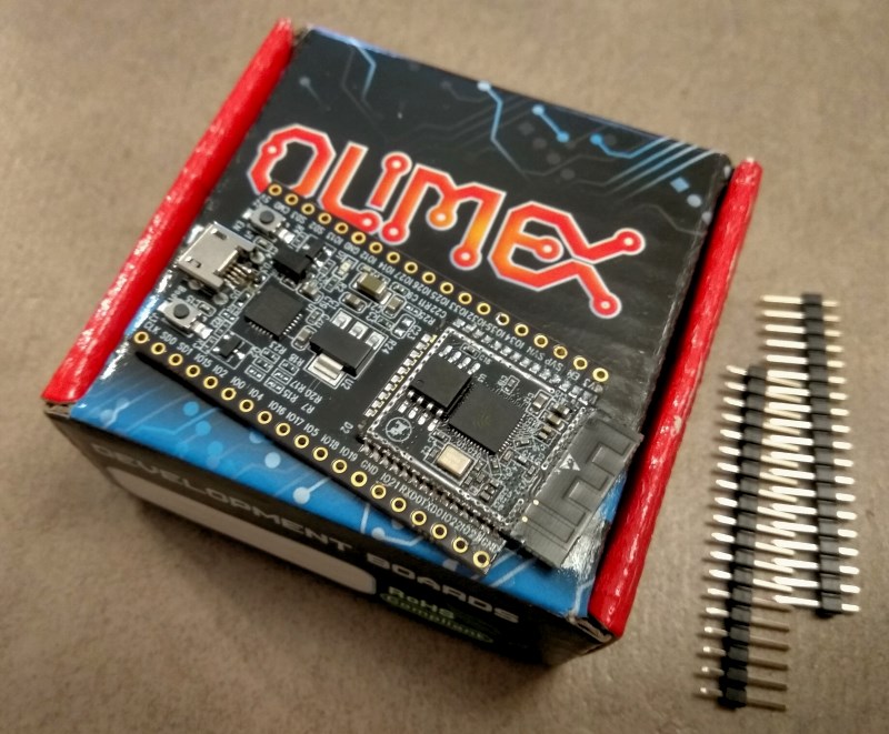
If you give a look to its schematics, you can find the ESP32 module, a voltage regulator (NCP1117) to lower the 5V coming from the USB bus to the 3.3V required by the chip, a CP2102 USB-to-serial adapter and two buttons. Moreover, all the most important PINs are available on the side connectors::

In the next post, you’ll learn how to install the development environment and how to write your first program!


