
In a previous blog post, I started explaining how to use the esp32 pins for Input/Output operations. Today I’ll show you how to take advantage of the interrupts the pins can generate.
Interrupts
In computer technology, an interrupt is a signal that indicates the occurrence of a specific event which requires immediate attention. The interrupt signal therefore blocks the normal program execution and runs a particular function, named interrupt service routine (ISR) which has the responsibility to react to the event that has occurred.
There are two kinds of interrupts: hardware and software.
[checklist]
- an hardware interrupt is generated by a peripheral external to the cpu (for example when a key is pressed down)
- a software interrupt is generated by a program running on the cpu (for example a device driver notifying new data available)
[/checklist]
GPIO interrupts
When used in GPIO mode, the esp32 pins have different conditions in which they can trigger an interrupt:
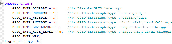
interrupts generated by I/O pins, gpio.h
Interrupts are generated based on the variations of the signal the pins are connected to. For example, if a pin is configured in GPIO_INTR_POSEDGE mode, an interrupt is triggered every time the signal changes from logic state 0 to logic state 1 (on the rising edge of the signal). At the opposite, if configured in GPIO_NEGEDGE mode, the interrupt is triggered on the falling edge of the signal (that is in the 1->0 change).
To configure the interrupt type for a pin, you can use the following function:
esp_err_t gpio_set_intr_type(gpio_num_t gpio_num, gpio_int_type_t intr_type); |
the parameters are the pin number (gpio_num) and the interrupt type (intr_type).
Alternatively, if you are configuring more pins at a time with a template, you can specify the interrupt type using one of the parameters the gpio_config_t struct offers:
typedef struct { [...] gpio_int_type_t intr_type; /*!< GPIO interrupt type */ } gpio_config_t; |
ISR and framework
As it was for pin management, the management of the interrupts in the esp32 chip is also quite complex: the chip offers indeed up to 32 interrupt slots for each core, with different priorities… Luckily, the framework really simplify the interrupts configuration.
First, you have to install the service that manages the interrupts for GPIO pins:
#define ESP_INTR_FLAG_DEFAULT 0 [...] gpio_install_isr_service(ESP_INTR_FLAG_DEFAULT); |
Then you can specify, for each pin, which is the interrupt service routine the cpu will run when the interrupt configured for that pin is triggered. You can also pass some parameters (args) to the ISR:
gpio_isr_handler_add(gpio_num, isr_handler, void* args); |
It’s very important to know that the interrupt service routine must have an execution time as short as possible, because it blocks the normal program execution.
ISR and tasks
I prepared an example to demonstrate the use of the interrupts and the correct way to write an interrupt service routine. The program, available on Github, waits – using an interrupt – until a button is pressed and then changes the status of a led.
Having used, as in the other examples of this tutorial, the ESP32 DevKit-C development board from Espressif, I took advantage of the BOOT button of the board, connected to the pin 0:
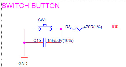
As you can see from the schematics above, when you press the button, the pin is connected to ground; I therefore have to use the GPIO_NEGEDGE interrupt type.
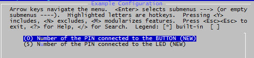
Both the pin connected to the button and the one connected to the led can be configured via menuconfig:
In the previous paragraph I explained that the ISR must have a short execution time; for this reason all the activities to be performed when the button is pressed have been moved to a dedicated task. It’s then important to understand how to make the ISR communicate with this task, to notify to it that the button has been pressed. FreeRTOS offers different ways to implement inter-task communication, from the simplest (semaphores, mutex…) to the most complex (queues…) ones. In my example I only need a binary notification (“button pressed”), I therefore chose to use a binary semaphore.

The following diagram explains how the program works:

First you have to create the semaphore:
SemaphoreHandle_t xSemaphore = NULL; [...] xSemaphore = xSemaphoreCreateBinary(); |
When the button is pressed, the ISR executed has the following code:
void IRAM_ATTR button_isr_handler(void* arg) { xSemaphoreGiveFromISR(xSemaphore, NULL); } |
It only “gives” the semaphore, or changes it status so a different task, waiting to “obtain” it, can get the semaphore and continue its execution.
The task that updates the led and the console has indeed the following code:
void button_task(void* arg) { for(;;) { if(xSemaphoreTake(xSemaphore,portMAX_DELAY) == pdTRUE) { printf("Button pressed!\n"); led_status = !led_status; gpio_set_level(CONFIG_LED_PIN, led_status); } } } |
An infinite loop that waits for the semaphore availability (portMAX_DELAY tells the function to wait an infinite time) and, when it can take the semaphore, displays the message Button pressed! on the serial port and toggles the led status.


Hi, just found your website and tutorials – they’ve been extremely helpful! Been looking for a resource like this for weeks. Much appreciated!
Luca, it means CONFIG_BUTTON_PIN and CONFIG_LED_PIN are defined for the board by default, right? Because there is barely any information about it. Could you please tell more where it is defined etc?
Adam, those are variables you can configure in menuconfig. Please give a look to my other tutorial about this functionality.
Hello Luca,
I see many of your tutorial related to esp32 which is quite interesting and informative too.
I try to understand your points mentioned on the blog specific to the topic. I really appreciate it.
What I thought would be great if you take a example and put a whole code together.
Thanks
Bhavik
Hi Bhavik, do you mean a “real” project based on my tutorials?