
STM32 is a family of 32bit microcontrollers manufactured by STMicroelectronics and based on the ARM Cortex M core.
The STM32 family is divided into different lines of microcontrollers (L0-1-4, F0-1-2…) depending on their features and the use they are designed for:

These microcontroller are widely used in the industrial world… for example both Pebble watches and Fitbit bracelets are based on STM32 MCUs.

Thanks to the work made by the stm32duino community and to the support of ST itself, starting from the past June STM32 microcontrollers can be easily used with the Arduino IDE and it’s also possible to take advantage of most of the libraries available for Arduino.
I decided to buy a minimal development board based on the STM32F103C8T6 microcontroller (these boards are sometimes known as blue pills); let’s see how to use it with Arduino.
Bootloader
Many boards are sold unprogrammed: the first thing to do is therefore to program a bootloader, that is a small program which will allow to upload the “real” program via USB port.
To flash the bootloader, you need an USB -> serial adapter, connected to your dev board as it follows:
- RX -> A9
- TX -> A10
- VCC -> 5V
- GND -> GND
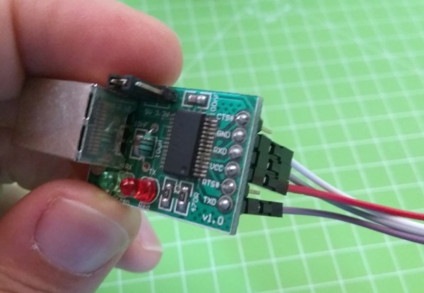

You have also to enable the programming mode, moving the first jumper (labeled BOOT0) to position 1:

Now you need a software to flash the file with the bootloader into the chip. If you’re under Windows, you can download the Flash Loader from ST’s official website: after having registered (for free) you’ll receive the download link via email.
The bootloader is developed and maintained by Roger Clark and it’s available in his Github repository. For STMF1 boards there are several binary files, depending on the PIN the onboard led is connected to. My board uses P13, so I downloaded the file generic_boot20_pb13.bin.
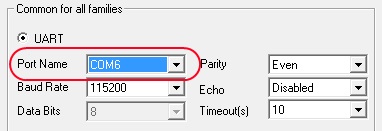
Run the Demonstrator GUI program and select the serial port your adapter is connected to:
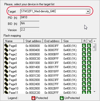
If all the connections are ok, the software should be able to detect the microcontroller:

Now you can select the specific MCU your board uses:
then select the file with the bootloader and program it. To be sure, you can ask the software to perform also a global erase of the memory:
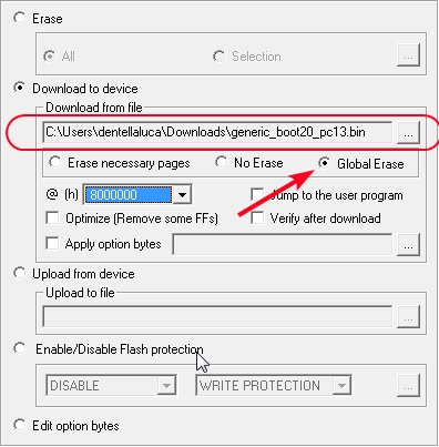
The program will flash the chip and, when complete, will confirm the operation with a message:
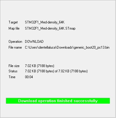
If you now move back the BOOT0 jumper to the original position, you should see the led blink: this means that the bootloader is running and can’t find a program to execute… now it’s time to configure the IDE.
Arduino IDE

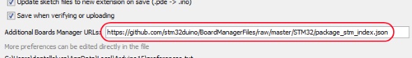
Open your IDE and select File – Preferences. Type the following address in the Additional Boards Manager URLs field:
https://github.com/stm32duino/BoardManagerFiles/raw/master/STM32/package_stm_index.json
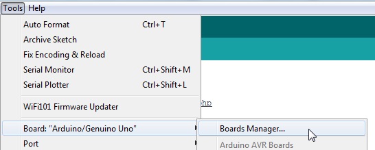
Now open the Boards Manager:
Search STM32F1 and install the corresponding Cores package:

You’re almost ready to compile and run your first program…
Drivers
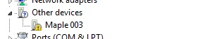
Connect the dev board to your PC using an USB cable and verify how it is identified.
It may happen that Windows cannot correctly identify the board and displays it as Maple 003, is this case you have to install the correct drivers:
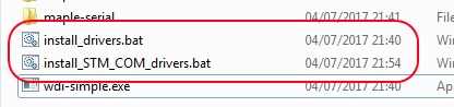
Download the following files from Clark’s repository:
- install_STM_COM_drivers.bat
- install_drivers.bat
- wdi-simple.exe
Run the two .bat:
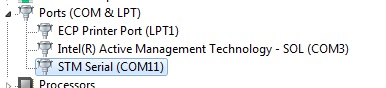
now Windows should identify the board correctly:

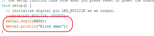
Sometimes Windows cannot see the additional serial port of the board. To solve the problem, you can try to program on the board a simple sketch that uses the Serial object. Open for example the blink sketch and change it as it follows:
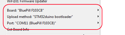
Program the sketch choosing BluePill F103C8 as board and STM32duino bootloader as upload method.
Once the sketch is programmed and executed, Windows should detect and install the new COM port:
You’re done, now the board is fully integrated with the Arduino IDE:


found the .bin file in Roger Clark’s repository, however when uploading the modified blink sketch:
Cannot run program “{runtime.tools.arm-none-eabi-gcc.path}\bin\arm-none-eabi-g++” (in directory “.”): CreateProcess error=2, The system cannot find the file specified
Hi, it usually means that the installation of the platform wasn’t successful… try to reinstall it.
Thanks for you wonderful manual!
I used Arduino IDE v 1.6.5 initially, which failed. Now I used v 1.8.3 that seems to do better. Using your directions, I could indeed persuade Windows to find the COM5 port. After compiling the blink sketch I see the following output, the STM32 is not programmed, (I use the USB line)
———————————–
Sketch uses 12172 bytes (9%) of program storage space. Maximum is 131071 bytes.
Global variables use 3012 bytes (36%) of dynamic memory, leaving 5180 bytes for local variables. Maximum is 8192 bytes.
STM32 ST-LINK CLI v2.1.0
STM32 ST-LINK Command Line Interface
No ST-LINK detected!
————————————
Sorry, ignore the output in my last comment. It is actually as follows: (the STM32 does not get programmed):
————————–
Build options changed, rebuilding all
Sketch uses 20276 bytes (30%) of program storage space. Maximum is 65536 bytes.
Global variables use 6456 bytes (31%) of dynamic memory, leaving 14024 bytes for local variables. Maximum is 20480 bytes.
maple_loader v0.1
Resetting to bootloader via DTR pulse
Searching for DFU device [1EAF:0003]…
Found it!
Opening USB Device 0x1eaf:0x0003…
Found Runtime: [0x1eaf:0x0003] devnum=1, cfg=0, intf=0, alt=2, name=”STM32duino bootloader v1.0 Upload to Flash 0x8002000″
Setting Configuration 1…
Claiming USB DFU Interface…
Setting Alternate Setting …
Determining device status: state = dfuIDLE, status = 0
dfuIDLE, continuing
Transfer Size = 0x0400
bytes_per_hash=411
Starting download: [##################################################] finished!
state(8) = dfuMANIFEST-WAIT-RESET, status(0) = No error condition is present
Done!
Resetting USB to switch back to runtime mode
error resetting after download: usb_reset: could not reset device, win error: The system cannot find the file specified.
———————————-
solved: problem was the 1.5 kΩ pullup resistor on D+ , see:
http://wiki.stm32duino.com/index.php?title=Blue_Pill
thanks for sharing your solution!
Grazie per la splendida guida! Ho due domande:
1) Le uscite e gli ingressi dei pin accettano 5v come arduino o 3.3v?
2)Ho bisogno di un conertitore seriale TTL?
Ciao Daniele, non tutti i pin sono 5v tolerant… puoi guardare il datasheet o questa tabella per sapere quali. Il convertitore seriale-ttl ti serve solo per programmare il bootloader, poi puoi usare l’interfaccia USB nativa.
Ciao Luca
GRAZIE tante per le tue spiegazioni molto utili.
io invece ho un problema….i miei IDE non trovano il file da caricare STM32F1 sul BOARDS MANAGER.
uso IDE 1.6.5 ed il 1.8.2
Trovano soltanto il STM32F4
se mi puoi aiutare ti ringrazierei tanto….
RAUL
Ciao! Controlla di aver inserito correttamente l’URL tra le “Additional Boards Manager URLs”, una volta scaricato l’elenco da quel sito dovrebbe comparire.
Ciao Luca, vorrei sapere se si può in qualche maniera installare sul IDE 1.0.6 l’applicazione per poterlo usare con questi CHIP stm32
Su PREFERENCES di questa versione IDE non c’è Additional Boards Manager URLs…!!
Ti saluto e ti ringrazio…!
RAUL
Ciao Raul, stai usando una versione veramente vecchia dell’IDE… devi aggiornarlo
ciao Luca…lo so, lavoro anche con la versione 1.8.3 ma questo codice che avevo fatto non si compila con i nuovi IDE ed io ancora sono un po di legno per capire il perché….
Comunque non si puo fare nulla con la versione 1.0.6….??? non posso caricare in nessuna maniera ..??
GRAZIE
RAUL
Ciao, ottima guida! Ho la stessa tua scheda di sviluppo, che però ho notato che monta oscillatori da 4 e 16Mhz, ti chiedevo se conosci un modo per capire a che reale frequenza vada questa MCU??? Utilizza un oscillatore interno per raggiungere i 70Mhz? Grazie!
ciao, il chip internamente va a 72MHz, che vengono generati a partire da un quarzo esterno (supportati da 4 a 16MHz) o dall’oscillatore interno a 8MHz.
Salve, ho una domanda. Ho acquistato una scheda BluePill, una volta scaricato il bootloader tramite ftdi volevo utilizzare la usb integrata sulla scheda, ma inserito il cavetto usb nel PC compare un pop-up di avvertimento dicendomi che l’ultimo dispositivo usb non è stato riconosciuto. Ho letto che potrebbe essere un problema hardware dato dalla resistenza posizionata su R10. Sostituendola con una resistenza da 1.8KOhm è possibile risolvere questo problema?
Ciao Jacopo, si alcune schede hanno questo problema e il suggerimento è proprio quello di cambiare la resistenza (vedi ad esempio la pagina wiki di STM32duino). Fammi sapere se così risolvi…
Buongiorno Luca,
intanto complimenti per il tuo impegno sulla condivisione.
Ho acquistato una scheda black pill STM32F103 ecc… ho seguito la tua procedura per far vedere la scheda in modalità seriale con demonstrator GUI della ST ma non me la riconosce.
Ho settato correttamente i jumper e settato l’interfaccia TTL/USB a 115200baud ma niente da fare.
Risulta a qualcuno un problema simile al mio?
grazie dell’aiuto
Antonio
È possibile utilizzare la scheda per correggere errori di rilevazione della temperatura di un termometro a infrarossi con processore stm32? O per ricalibrare la temperatura minima con l’emissione sonora del bip ?
non penso… per fare quello che chiedi sarebbe necessario riprogrammare il termometro avendo a disposizione il firmware originale o addirittura riscrivendolo da zero
Buongiorno Luca, Ottima guida complimenti.
Io ho una blue pill STM32F103C8, ho seguito tutti i passi elencati, però anche se l’ide di arduino riconosce la scheda non mi da STM32duino bootloader come upload method, ci sono 3 opzioni ma non quella che serve . non so che fare . Ciao
Ciao, il tutorial ormai è superato per i nuovi IDE, segui la wiki ufficiale
Grazie. Ciao
Risolto : Bisogna scaricare il file (Arduino_STM32-master.zip) dal wiki ufficiale
qui ( http://wiki.stm32duino.com/index.php?title=Installation ) decomprimere e mettere la cartella : Arduino_STM32-master (togliendo -master) qui : C:\Users\\Documents\Arduino\hardware\Arduino_STM32 , aggiungere” \hardware” se non è presente . Riavviare ide arduino . Adesso il upload method : STM32duino bootloader è presente ed è possibile caricare gli sketch .
Grazie Luca
Il tutorial non è superato c’è solo da aggiungere quest’ultima parte . Ciao
grazie Giancarlo per il feedback!
Buon giorno,
sto usando una scheda STM Nucleo-32 modello 32L4KC.
Ho installato correttamente tutte le librerie, gli esempi base funzionano senza alcun problema.
Quando compilo un mio software che su Arduino classico funziona senza alcun problema, così come su un altro microcontrollere, ottengo questo errore:
C:\Users\skunkworks2\AppData\Local\Arduino15\packages\STM32\hardware\stm32\1.5.0\libraries\Wire\src/Wire.h:54:5: error: ‘i2c_t’ does not name a type
i2c_t _i2c;
Mi può aiutare?
Grazie. Silvano
Complimenti,
molto interessante e ben esposto.
Io avrei intenzione di spiegare a dei ragazzi del fablab (maker village) di Genova l’utilizzo della nucleo STM32F303RE in alternativa ad arduino, per i progetti che necessitino performance maggiori.
Purtroppo ho seguito diversi tutorial, arrivo alla fine selezionando la scheda ma nell’UPLOAD non appare stlink ma memoria di massa (di default) ed altre opzioni e poi non mi compila, dandomi errore di spazio non sufficiente nel disco.
Premetto che vedo nella gestione dispositivi di W10 la stlink sotto la com 16.
Immagino ce il quadro non sia sufficiente a dare un parere ma può darsi anche di sì.
Grazie
Antonio
buongiorno Antonio, il tutorial sul mio sito è ormai obsoleto, nel frattempo ST ha rilasciato il core ufficiale per Arduino.
Ho provato al volo seguendo la guida ufficiale e tutto ha funzionato. Tieni presente che – come scritto nella wiki – le nucleo già integrano un ST-Link ed è quindi normale che ti proponga mass storage (è anche la modalità più comoda perché ti basta un drag’n’drop del file per programmare la scheda). Per il problema di compilazione non saprei dirti: ho appena provato un semplice “blink” scaricando da zero il core e funziona tranquillamente (anche io Win10).