
In this tutorial, divided in two posts, I’ll show you how to use RFID (Radio-frequency Identification) tags with Arduino.
In the first part you’ll learn how to connect the reader to your Arduino and how to write a simple sketch to display the tag’s ID, while in the second part you’ll learn how to build a complete access control system based on RFID tags.
PN532
I chose as RFID reader a board based on the PN532 chip by NXP. This is a very versatile chip: it can work as a tag reader/writer but it can also act as a RFID tag; moreover it supports both I2C and SPI communication buses.
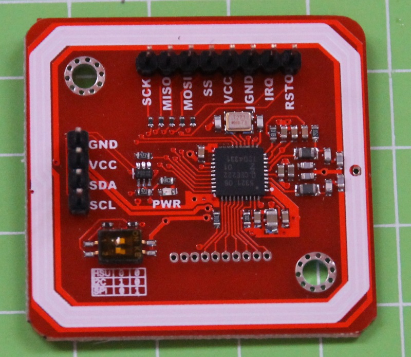
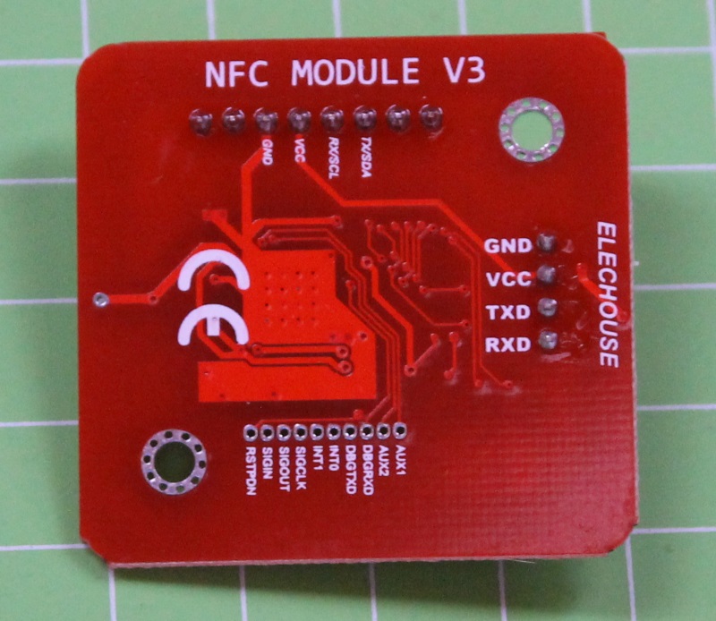
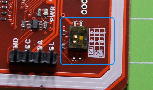
Adafruit created a breakout board for the PN532 chip and the Arduino libraries we’re going to use. Alternatively you can find on several webstores the following board, that I’m also going to use for this tutorial:
Connections
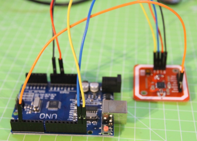
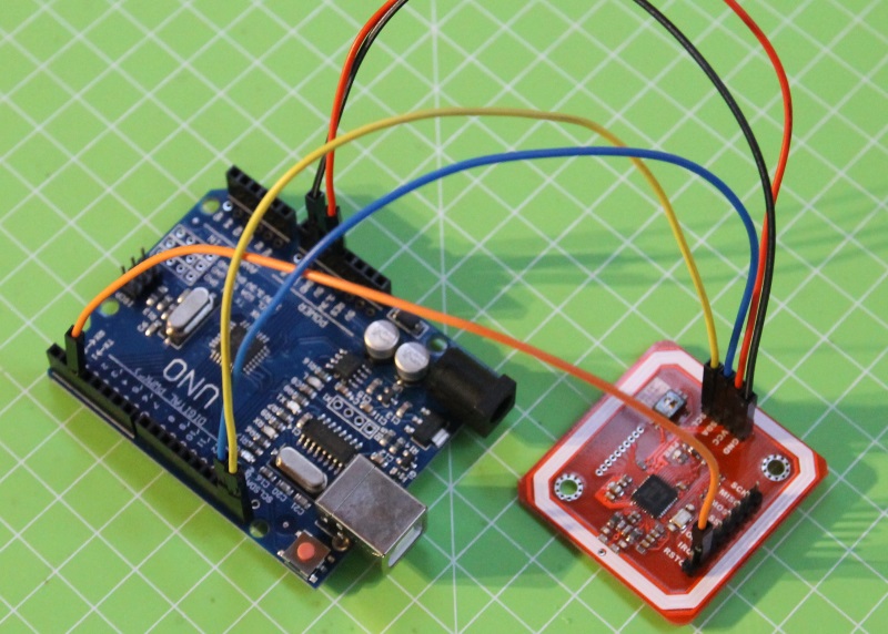
As I wrote before, the PN532 chip supports both I2C and SPI. For simplicity, I’ll use the first one, connecting the SDA and SCL pins of the board to the corresponding pins of Arduino. You have also to connect the IRQ pin to a digital pin of your Arduino (I chose pin 2); thanks to this connection the PN532 pin “warns” Arduino if a new tag is being read:
To select the I2C bus, you have to set the board’s dip switches as explained on the silk screen:
Finally, power the board connecting the VCC and GND pins to pins 5V and GND of Arduino.
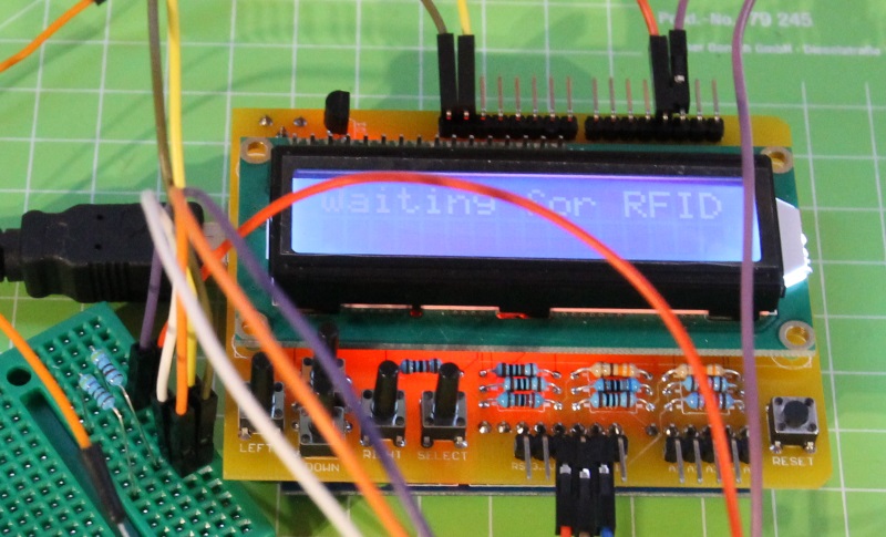
For this project, I used the beta version of a new LCD shield by Lemontech. The main feature of this shield is that the LCD is connected to Arduino via an I2C expander; moreover all the buttons are connected to only one pin, the analog pin A0. This means that almost all the Arduino pins are still available for connecing other devices. The display’s default address – but you can change it – is 0x27 while the PN532 chip has address 0x24 so there’s no conflict.

Having two devices connected to the I2C bus, I had to add two 10Kohm pull-up resistors for SCL and SDA as explained in the following schematics:
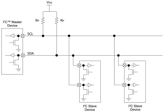
To keep things simple, I place them on a small breadboard:

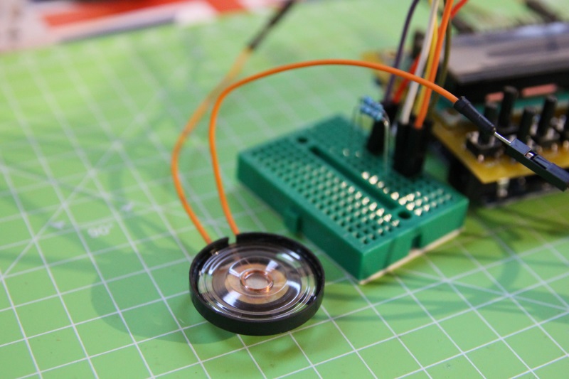
I also added a small speaker (connected to pin 8 and GND) to play a sound everytime Arduino reads a tag:
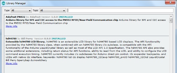
Libraries
To be able to compile the sketch of this tutorial you have to install the following libraries in your IDE:
- Adafruit PN532 di Adafruit
- hd44780 di Bill Perry
Both the libraries are available in the Library Manager:
Sketch
The complete sketch is available in my Github repository.
To use the LCD, first you have to define its size (rows and columns), the address on the I2C bus and the pins it’s connected to. You can then initialize the library in the setup():
#define LCD_COLS 16 #define LCD_ROWS 2 hd44780_I2Cexp lcd(0x27, I2Cexp_PCF8574, 0,1,2,4,5,6,7,3,HIGH); [...] if(lcd.begin(LCD_COLS, LCD_ROWS) != 0) { Serial.println("- Unable to initialize LCD!"); while(1); } |
The same for the PN532 chip: you have to declare the pin connected to the IRQ signal (RESET is optional) and then initialize it. Using the getFirmwareVersion method you can get the chip version and therefore verify that it’s working correctly:
#define PN532_IRQ 2 #define PN532_RESET 3 Adafruit_PN532 nfc(PN532_IRQ, PN532_RESET); [...] nfc.begin(); uint32_t versiondata = nfc.getFirmwareVersion(); if(!versiondata) { Serial.println("- Unable to find a PN532 board"); while(1); } Serial.print("- found chip PN5"); Serial.println((versiondata>>24) & 0xFF, HEX); |
Lastly, call the SAMConfig() method to configure the chip in normal mode and to enable the IRQ pin:

It’s very easy to read a tag. The readPassiveTargetID method returns true if a tag is near the reader:
success = nfc.readPassiveTargetID(PN532_MIFARE_ISO14443A, uid, &uidLength); if (success) { |
In this case, you can play a sound and display the tag’s ID on the display:
tone(SPEAKER_PIN, TONE_FREQ, TONE_TIME); lcd.clear(); lcd.print("Found RFID tag!"); lcd.setCursor(1,2); lcd.print("ID: 0x"); for(int i = 0; i < uidLength; i++) { if(uid[i] <= 0xF) lcd.print("0"); lcd.print(uid[i] & 0xFF, HEX); } |


I noticed that you used manual configuration for the hd44780_I2Cexp constructor. Was the library not able to auto detect the parameters correctly?
If so, I’d like to see the schematic of the PCB for the LCD i/o expander to understand why it is failing.
BTW, hd44780 not contains a fatalError() function that can be called to indicate a fatal error code. hd44780::fatalError(errorcode);
If there is an onboard LED, it will blink the error code. See the HelloWorld
sketch for how to use it.
Hi, I had to manually configure the library because there’s another device connected to the i2c bus and this “disturbed” the autoconfig routine.
Buongiorno Luca,
sto impazzendo con il tuo progetto.
Ho acquistato il modulo NFC identico a quello utilizzato da te, ma non riesco a farlo funzionare.
Anche utilizzando gli esempi presenti nella libreria, il modulo si accende ma non comunica con arduino.
Potrebbe essere che sia guasto il modulo?
Come posso verificare il funzionamento?
Ti ringrazio per l’attenzione.
ciao Mauro! Sicuramente può essere rotto… prova a vedere se almeno è “raggiungibile” sul bus i2c. Esegui su Arduino lo sketch i2cScanner, il chip PN532 dovrebbe essere trovato sull’indirizzo 0x48.
Ciao Luca e complimenti. Vorrei realizzare un controllo accessi che legga non solo dei tag nfc ma anche ìlnfc di uno smartphone android così da usare il cellulare per accedere e attivare un relè apri porta.
Questo RP532 legge l’nfc di uno smartphone ? il modulo rc522 sembrerebbe che non legga l’nfc
buongiorno Graziano, non ho mai provato (non ho uno smartphone compatibile) ma da quanto leggo dovrebbe funzionare, ad esempio è citato nella guida di Seeedstudio.
Complimenti Luca,
come faccio invece se voglio vedere il contenuto della mia scheda RIFD, il mio intento è quello di poterci scrivere sopra in maniera molto veloce.
Ora per le mie schede uso lo smartphone con l’app Mifare Classic Tool con i quale vado a modificare il contenuto dei primi due byte del settore 2. L’ideale sarebbe poter tramite arduino, la PN532, e poi come comandi posso usare una shield simile alla tua che ho già in mio possesso con i tasti e display 16*2.
ciao Michele, ti consiglio uno degli ottimi tutorial che si trovano in rete…