
Today’s project, ESP32lights, is a smart device based on the esp32 chip.

Thanks to ESP32lights you can turn a load on and off (I used it for my christmas lights)
[checklist]
- manually
- based on daily schedules
- based on the light intensity
[/checklist]
ESP32lights connects to your wifi network, can be configured and operated via a web browser and it’s optimized for mobile devices (responsive web interface based on jQuery Mobile).
Components
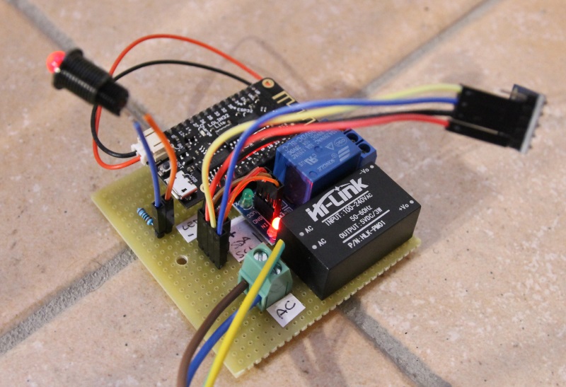
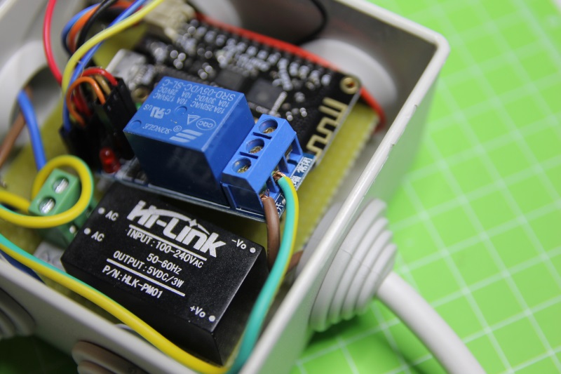
The heart of ESP32lights is the Lolin32 Lite devboard by Wemos. One of its digital pins is connected to a relay module, which controls the load. Two digital pins are assigned to the first i2c controller of the esp32 chip and are connected to a BH1750 light intensity sensor. All the elements are powered by an HLK-PM01 module by Hi-Link, which directly converts the mains’ 220V AC to 5V DC without the need of any external components:

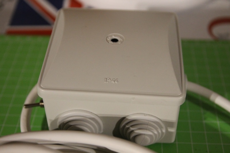
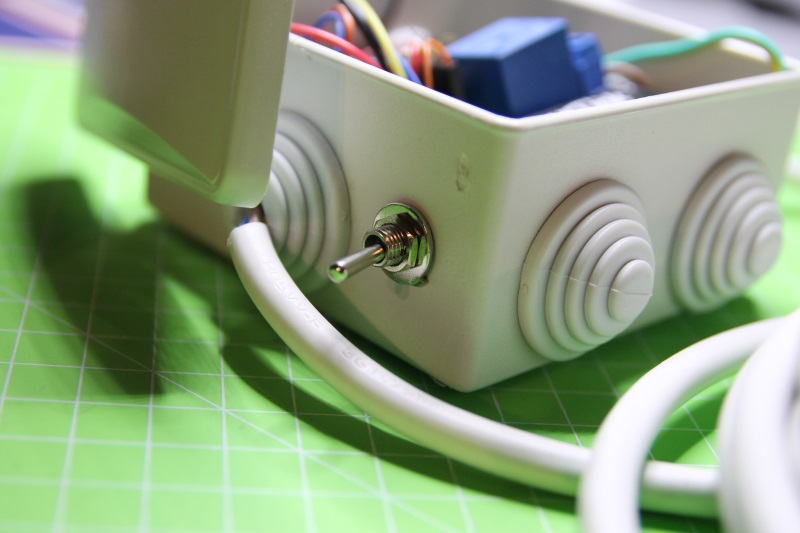
All the components are placed in a waterproof enclosure, to be able to use the device outdoor:

Programming
The firmware for the esp32 devboard is available in my Github repository.
In a following paragraph I’ll explain how it works. If you just want to build the device, you can program the firmware as it follows:
1) clone my repository in a local folder of your PC (you also have to install the development env esp-idf):
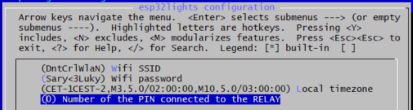
2) configure the correct settings for your wifi network and your timezone via menuconfig:
3) compile and flash the firmware:
make flash
4) store the image of the SPIFFS partition into the flash memory (replace the COM port of your devboard and the path where you saved the img file):
python $IDF_PATH/components/esptool_py/esptool/esptool.py --chip esp32 --port COM15
 --baud 115200 write_flash --flash_size detect 0x180000 /home/esp32lights.img
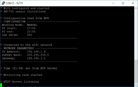
If everything is ok, when you connect to the serial console of the devboard (make monitor) you should see the following output:
Use
ESP32light publishes an HTTP interface you can use to set the schedules or the light intensity threshold or to manually turn the load on and off.
You can open the web interface connecting – through a PC or a smartphone -to the address http://<esp_ip> (the IP address of the board is displayed in the serial output as shown in the previous paragraph).
The interface has 3 tabs, one for each working mode:
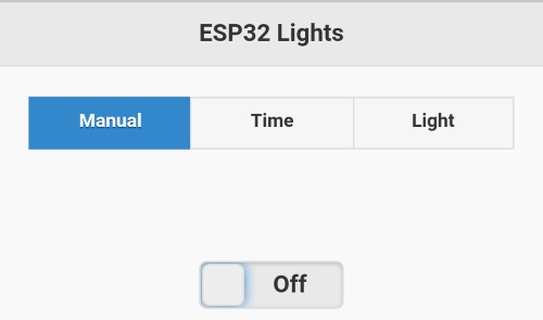
The page footer displays the actual working mode and the relay status:

In this short video, you can see how the device works:
Software
I developed the firmware for ESP32lights leveraging what I explained in my previous tutorials about the esp32 chip. If you follow my blog, you probably understood that I really like the divide et impera method, that is divide a complex project into small, simpler tasks.
All the configuration settings of ESP32lights (actual working mode, start and stop time…) are stored in the NVS partition of the flash memory, as I explained in this tutorial. In this way, it’s possible to keep them even if the chip is restarted:
nvs_handle my_handle; int working_mode; [...] esp_err_t err = nvs_flash_init(); err = nvs_open("storage", NVS_READWRITE, &my_handle); err = nvs_get_i32(my_handle, "mode", &working_mode); |
The different elements of the web interface (html page, css style sheets…) are stored in an SPIFFS partition. In a previous tutorial you learned how to prepare the image and, in your program, get its content:

In other tutorials I’ve also already explained you how to connect to a wifi network and how to use digital pins.
The setup phase is completed after having configured the BH1750 light intensity sensor. This sensor offers an i2c interface and therefore can be connected to one of the two i2c controllers of the esp32 chip as shown in this tutorial. In my program I included a driver developed by pcbreflux.
The main program runs two different tasks:
xTaskCreate(&http_server, "http_server", 20000, NULL, 5, NULL); xTaskCreate(&monitoring_task, "monitoring_task", 2048, NULL, 5, NULL); |

The first one publishes the web interface, while the second one verifies – every second – if conditions exist (time or light intensity) to turn the load on or off:
if(working_mode == MODE_LIGHT && lux_valid) { int actual_light_value = get_light_value(); if(actual_light_value < lux) { if(relay_status == false) { gpio_set_level(CONFIG_RELAY_PIN, 1); relay_status = true; } |
Here’s in details how the http server fetches a static resource, stored in the SPIFFS partition.
First it adds to the resource path the root prefix for the SPIFFS partition (/spiffs):
sprintf(full_path, "/spiffs%s", resource); |
then it checks if the resource exists in the partition:
if (stat(full_path, &st) == 0) { |
if so, it opens the file in read mode:
FILE* f = fopen(full_path, "r"); |
and sends the content of the file to the client, reading blocks of 500 bytes:
char buffer[500]; while(fgets(buffer, 500, f)) { netconn_write(conn, buffer, strlen(buffer), NETCONN_NOCOPY); } |
Finally, this is how the web interface works. The interface is made by an html page (index.html) which uses jQuery to perform AJAX requests to the server and update the different page elements. You don’t need to enter the page name in the browser because of the http server automatically performs a redirect to it if the default page is requested:
if(strstr(request_line, "GET / ")) spiffs_serve("/index.html", conn); |
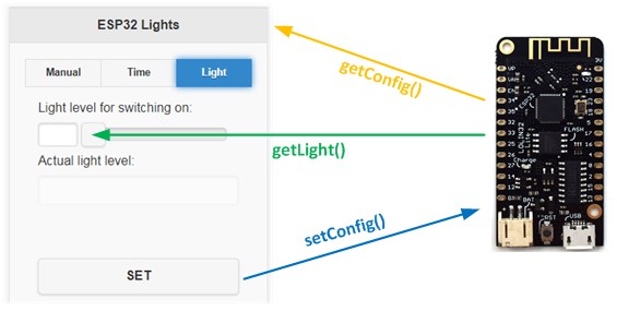
3 endpoints are published by the server and accessed using AJAX calls::
[checklist]
- setConfig, to send a new configuration
- getConfig, to read the actual configuration
- getLight, to get the actual light intensity
[/checklist]
When the page is loaded, it calls the getConfig endpoint to display the actual configuration; moreover it schedules every 5 seconds a call to the getLight endpoint to keep the light value updated:
refreshConfig(); setInterval("refreshLightLevel()", 5000); |
When you click on the SET button, the page calls setConfig to send to the server the new configuration:
All the information are sent using the JSON format. The esp-idf framework includes the cJSON library which makes it easy to create or parse a json message:
cJSON *root = cJSON_Parse(body); cJSON *mode_item = cJSON_GetObjectItemCaseSensitive(root, "mode"); [...] cJSON *root = cJSON_CreateObject(); cJSON_AddNumberToObject(root, "lux", light_value); char *rendered = cJSON_Print(root); |
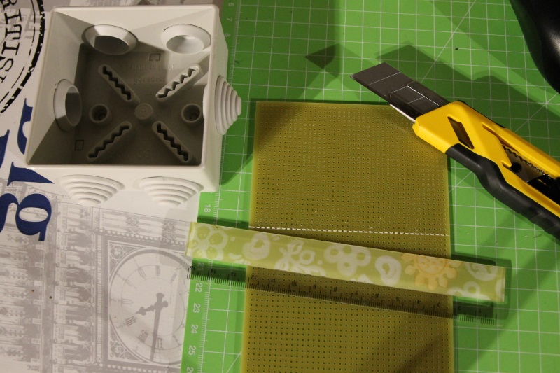
Making of
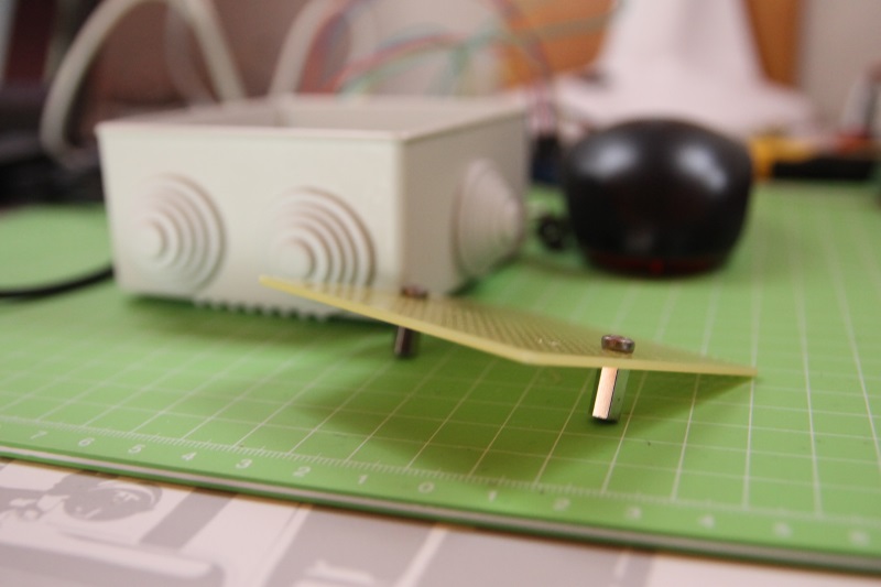
I started the build of the device cutting a perfboard to the size of the enclosure:
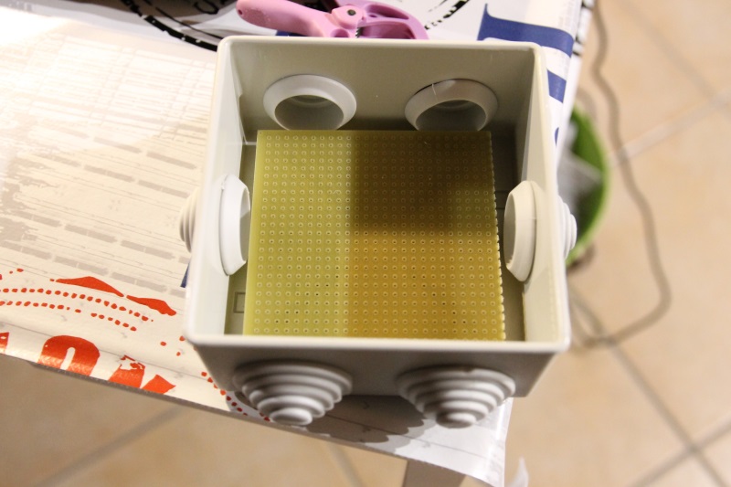
The perfboard is screwed to the enclosure using two spacers:

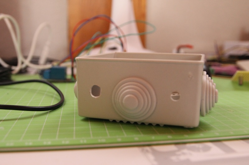
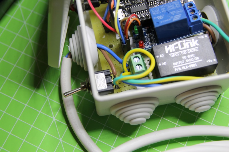
I made two holes in one side of the enclosure for the main switch and for a status led:
I soldered all the different components on the perfboard and made the electric connections using wires:
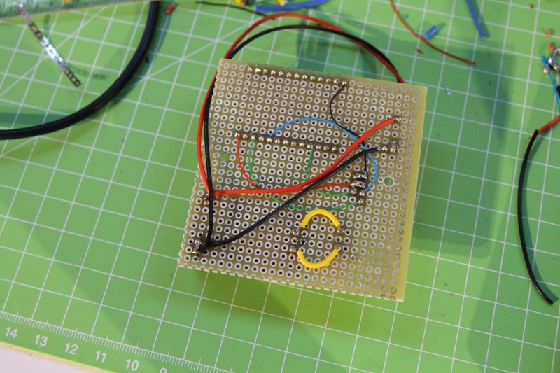

To simplify the installation, all the external components (led, relay module…) are connected using jumpers:


First test:
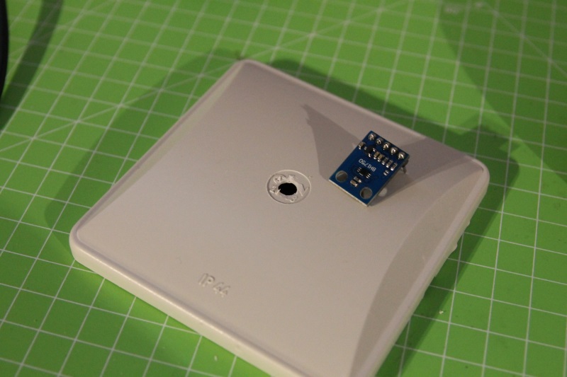
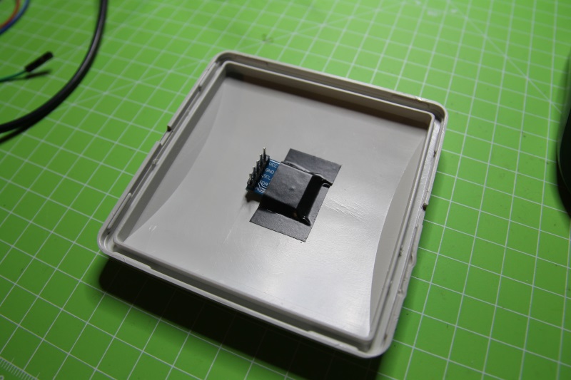
I attached the light sensor to the top of the enclosure, after having made a hole to allow it to “see” the external light:
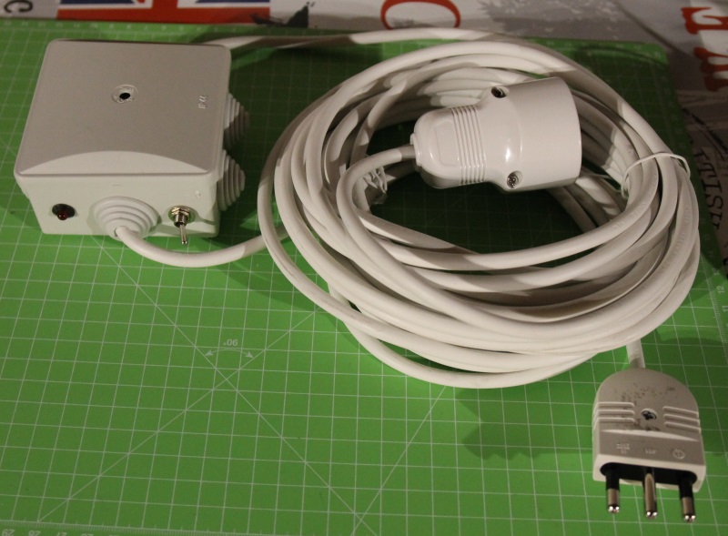
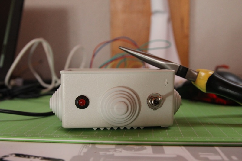
Finally I made the external connections, installing the main switch:
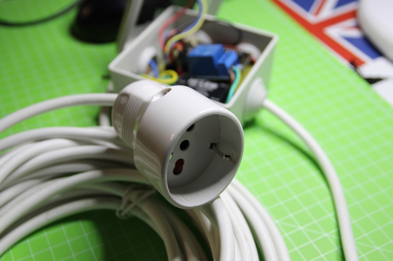
and connecting the output of the relay module to a wire with an universal plug at its end:


Hello, I see that you use a lot that AC/DC convertor. Are you satisfied with it. I just started using one for an ESP8266 project and so far no smoke and everything seems to work fine. Did you have any issues with them?
Thank you.
Hi, so far the AC/DC modules I used in my projects worked great! No issues at all!
Thank you, I hope that mine will do just fine too. Great work.
hi, Luca, i am in China and we want develop a device using ESP32 as the WIFI module. we have a device needs to be controlled remotelly with mobile phone. do you know any company or ppl who is good at this ESP32 based development?
Thanks.
Hi Tom, try asking on esp32.com, it’s the “official” forum and there are freelancers who regularly write on it
thanks, i will go for it.
Economics of scale kicking in. A 1A USB charger is much cheaper than the Hi-Link module, and is about the same size.
The build quality is questionable and you have to pot them yourself then of course, but I have had good luck with them in similar applications.
If you really wanted to get cheap since your design can be entirely isolated: Switch your relay out for a logic level triac and you can then drive this directly from mains with just two capacitors, a switching diode, and a zener. This comes with the warning that one leg of the ESP32 will be at mains level then so no human contact allowed once in circuit, and triac failure will likely fry the ESP32.
Hi Daren, thanks for your suggestions! To be honest I had some Hi-Link modules laying around and I this was a good project to test them.
Hi Luca, great project, is there anywhere that describes how the data in the webapp is accessed by the esp32 ?
js and web development is not my strongpoint by any stretch
thanks ! keep up the good work
ah sorry, ignore my question i hadn’t got that far down the article 🙂
Your Hi-Link is dead!
Thanks Ted, now fixed
Ciao Luca, chiaro come sempre: avrei una domanda sul relay.. I 5 v per la bobina sono presi dalla esp32 board ma il pin per azionare il relay è a 3.3 v (uscita della scheda) : non hai paura che bruci la scheda (oppure hai tolto il jumper vcc che si trova sul relay e alimentazione e controllo sono su 2 linee separate?)
Per farla breve si può connettere in maniera così semplice un relay 5 v dc alla scheda esp32?
Grazie in anticipo della risposta
Mauro
Ciao Mauro! In effetti il relay è dichiarato a 5v (avevo solo quello) ma “scatta” anche se lo controlli a 3.3V… non c’è rischio di bruciare la scheda, al massimo se la tensione non è sufficiente il relay non si aziona.
Hi Luca,
Great project, it is almost exactly what I was looking for.
I had a timer for years that turns the lights on when it gets dark, and turns it off at given time so it won’t be on until the morning. Since I am not a programmer, I want to ask you if your program can be modified to do that. It would be of great help to me since the timer I used is EOL and there are no replacements for a usable price.
Thanks.
Hi Herman, you should be able to modify the program… to keep it simple you could use one of the time fields already present in the GUI to set the “off” time instead of designing a dedicated GUI (more complex)
Ciao Luca, grazie per la condivisione del progetto.
Ho un dubbio sui collegamenti elettrici.
l’uscita massa e +5 volt del convertitore su quali pin della scheda lolin32 li collego?
A me sembra che questa scheda si alimenti solo dalla presa usb.
Tu come li hai collegati?
Infine confermami per cortesia gli altri pin di collegamento che sono pin 0=comando relè, il 4=SCL il 16=SDA del sensore BH1750.
Grazie mille in anticipo.
Felice.
Ciao Felice, ho utilizzato il connettore batteria (vedi questa immagine). Il pin del relay lo configuri da menuconfig, mentre quelli del sensore sono i pin 18 e 19 (ma li puoi cambiare editando bh1750.c
Ciao Luca, ieri ho inserito una richiesta, vorrei solo sapere se è stata ricevuta, grazie.
Massimo
ciao massimo, no non ho ricevuto nulla… mi hai scritto tramite form?
Ciao Luca. Sei grande.Bravo. Un rumeno chi aprezza tuo lavoro.
grazie mille!
Ciao Luca,
grazie per le spiegazioni molto chiare!
Ho un problema con il file .img della partizione SPIFFS relativa ai files css e html.
Se utilizzo quello incluso nel progetto tutto funziona correttamente, mentre semplicemente rigenerando il file .img con i comandi da te indicati nel tutorial, ottengo un file binariamente differente rispetto all’originale con l’effetto di non riuscire ad avviare la pagina web dal browser
Hai qualche consiglio sulla origine delle differenze?
Grazie
Roberto
ciao Roberto, a partire da una certa versione in avanti, espressif ha “rotto” la compatibilità con l’utility mkspiffs… quale versione stai usando?
Ciao Luca,
ho scaricato e compilato la versione dal link
https://github.com/loboris/ESP32_spiffs_example
per generare il file di creazione dei file immagine .img
Per quanto riguarda i files da allegare al progetto ho lasciato quelli da te inclusi nel progetto (cartella firmware\components\spiffs\).
ciao Roberto, prova ad aggiornare anche la libreria spiffs che sta nella sottocartella components, probabilmente se usi la versione più recente di mkspiff devi usare anche la libreria relativa
Ciao Luca,
problema risolto.
L’origine del problema era il disallineamento tra i files spiffs_config.h: il primo necessario per generare il file mkspiffs.exe di creazione della immagine .img , il secondo quello per accedere tramite applicazione scaricata su esp32 ai files contenuti nell’immagine stessa.
Roberto
Ciao Roberto volevo chiederti un chiarimento: come capitato a te provando a creare una nuovo file .img non visualizzo i contenuti sul web browser.
Hai accennato a un problema di disallineamento dei file spiffs_config.h.
Puoi spiegarmi in dettaglio quale operazione hai effettuato ?
Ciao Nicola,
io avevo trovato una differente definizione dei parametri
SPIFFS_OBJ_META_LEN
SPIFFS_USE_MAGIC_LENGTH
SPIFFS_ALIGNED_OBJECT_INDEX_TABLES
tra il progetto di Luca e quanto scaricato da internet, necessario per generare il file mkspiffs.exe.
Ti consiglio di mettere alcune std::cout nel main per stampare dette defines, ricompilare ed eseguire mkspiffs.exe: in questo modo potrai vedere con quali parametri sta creando l’immagine il software mkspiffs.exe e confrontarli con quelli del tuo progetto. io me ne sono accorto in questo modo.
Ciao Luca
Sto sviluppando un progetto simile al tuo che in pratica prevede che dei relè siano comandati da un’app e ho già sviluppato tutto. La mia domanda è la seguente: dato che usi in questo progetto un relè uguale al mio per comandare la 220. Dovrei pilotare un carico di circa 10A sulla 220AC, secondo te va bene o esplode? Ho anche preso, sempre made in cina, un relè più grosso, che indica 30A o 1/2 HP su 240VAC. In pratica dovrei comandare due motori elettrici, uno da 0,6HP e uno da 1 HP credo che neanche il relè più grosso vada bene o sbaglio?
Aspettavo anche una tua risposta sul progetto al link
http://www.lucadentella.it/2015/09/12/collegare-arduino-a-dispositivi-a-3-3v/