
One of the major concerns for embedded devices is the power consumption. If the device you’re designing will be battery powered, it’s indeed important to reduce as much as possible its power consumption to maximize the autonomy (= the working time before it’s necessary to replace or recharge the battery).
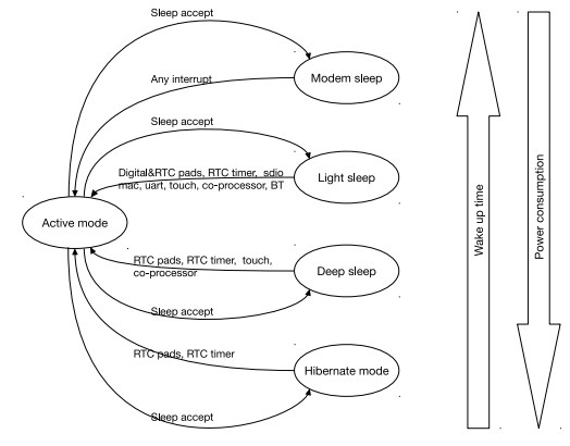
The esp32 chip offers 5 different power modes. The “normal” mode is named active mode; in this mode all the features of the chip are available. By starting to reduce the CPU speed and disabling some peripherals and cores, the chip switches to different power saving modes, as summarized in the following diagram:
In this first post about the esp32 power saving modes, I’ll explain the deep sleep mode.
Deep sleep
The esp-idf framework actually supports two power saving modes: light sleep and deep sleep. Between the two, the deep sleep mode is the one which offers greater energy savings. In this mode, are turned off:
[badlist]
- both the CPUs
- most of the RAM memory
- all the peripherals
[/badlist]
by default are instead kept active:
[checklist]
- the RTC controller
- the RTC peripherals, including the ULP coprocessor
- the RTC memories (slow e fast)
[/checklist]
You can put the chip in deep sleep with the esp_deep_sleep_start() method, while it’s possible to wake up it via different events:

When the chip wakes up from deep sleep, a new boot sequence is performed. It’s therefore very important to understand that the execution of your program does not restart at the point where the esp_deep_sleep_start() method is called.
Let’s see how to configure and use two wake up events; in a future post I’ll write about touch pad and ULP.
Timer
The simplest wake up event is for sure the one which leverages a timer of the RTC controller. Thanks to the method:
esp_err_t esp_sleep_enable_timer_wakeup(uint64_t time_in_us) |
you can wake up the esp32 chip after the specified number of milliseconds. The method must be called before entering the deep sleep mode:
// wakeup after 10 seconds esp_sleep_enable_timer_wakeup(10000000); esp_deep_sleep_start(); |
I/O triggers
In a previous post I’ve already blogged about the possibility to receive interrupts when a digital pin of the chip changes its status. We can leverage a similar functionality to wake up the chip from sleep.
With the method
esp_err_t esp_sleep_enable_ext0_wakeup(gpio_num_t gpio_num, int level) |
you can enable the wake up if the specified pin (gpio_num) changes its status (level).
You can only use the pins with RTC function (0, 2, 4, 12-15, 25-27, 32-39) and the possible levels are 0 (= low) or 1 (high). If, for example, you want to wake up the chip from deep sleep if pin 4 has a low level, you’ll write:
esp_sleep_enable_ext0_wakeup(4, 0); |
The framework also offers a method to monitor different pins:
esp_err_t esp_sleep_enable_ext1_wakeup(uint64_t mask, esp_sleep_ext1_wakeup_mode_t mode) |
the pins (this method also accepts only the ones specified above) must be specified in a bitmask and the wakeup modes are:
- ESP_EXT1_WAKEUP_ALL_LOW = wakeup when all the pins are low
- ESP_EXT1_WAKEUP_ANY_HIGH = wakeup when at least one pin is high

After the wake up…
If you configured more than one wake up event, you can know which specific event woke up the chip with:
esp_sleep_wakeup_cause_t esp_sleep_get_wakeup_cause() |
The possible constants are:

For the ext1_wakeup event, a specific method is available to get the bitmask of the pins:
uint64_t esp_sleep_get_ext1_wakeup_status() |
Memory
As explained above, in deep sleep mode the content of the RTC fast and RTC slow memories is preserved. You can therefore use those memory segments to store data that must be retained during the sleep.
To ask the compiler to store a variable in the RTC slow memory, you can use the RTC_DATA_ATTR attribute, or the RTC_RODATA_ATTR one if the variable is read only:
RTC_DATA_ATTR static time_t last; |
Demo
I wrote a program (its source code is in my Github repository) to demonstrate the deep sleep mode and two different wake up events:


i have trouble with the deepsleep of the esp32 (huzzah32)
I hope any one of you could help me.
i am using this:
switch (esp_deep_sleep_get_wakeup_cause()) {
case ESP_DEEP_SLEEP_WAKEUP_EXT1: {
uint64_t wakeup_pin_mask = esp_deep_sleep_get_ext1_wakeup_status();
if (wakeup_pin_mask != 0) {
int pin = __builtin_ffsll(wakeup_pin_mask) – 1;
printf(“Wake up from GPIO %d\n”, pin);
} else {
printf(“Wake up from GPIO\n”);
}
break;
}
and get the following error:
“error: esp_deep_sleep_get_ext1_wakeup_status() not declared in this scope”
I include deepsleep:
#include
Did anyone had an hint for me?
Thanks a lot!!
Regards,
Stivi
Hi, it seems they changed the method to esp_sleep_get_ext1_wakeup_status()
Thanks a lot Luca! You made my day!
I haven´t seen it!
It´s working now!
Ciao Luca,
Grazie del tuo video, mi sarà molto di aiuto nel progettino che sto realizzando. Vorrei costruire un tastierino wireless bluetooth usando un comune matrix keypad a membrana e ESP32. Il mio problema è che vorrei sfruttare il deep sleep e risvegliare il dispositivo solo quando l’utente digita qualche tasto. Mi accontenterei anche di perdere la prima cifra digitata eventualmente. Tu che consigli mi daresti per realizzare questa cosa? Grazie mille!
Ciao Alessandro, quei tastierini normalmente sono gestiti come “matrice”, quindi penso si possa usare il wake sui pin di I/O a cui hai collegato il tastierino! buon diverimento!
Si certo, però il problema è che dato che sono gestiti a matrice, per poter capire quale tasto è stato premuto, si cicla sulle righe (collegate ai pin di output) e si da livello logico alto, andando poi a leggere le colonne per capire quale tasto è stato premuto. Per questo motivo, diversamente dal pushbutton che è sempre “alimentato”, gli switch della matrice sono alimentati a rotazione ma solo mentre il codice è in esecuzione. Forse ho capito male io, me lo confermi? Grazie ancora!
Any compatibility with Time.h Library?
Hi, if you’re referring to Arduino Time library, sorry but my tutorials are not for Arduino
Yes, this library is for Arduino, but it can use with ESP32.
In general words, ¿can we store real time variables in deep-sleep mode?
Ciao,
avrei bisogno di un consiglio.
Sto cercando di realizzare la classica stazione meteo con una scheda Lolin32 Lite, collegata ad un oled 0,91, un sensore bme280 e un sensore mq-2.
A livello di codice il tutto funziona ma il problema nasce quando mando in deep-sleep la scheda.
Vorrei spegnere anche le periferiche, soprattutto i due led sul sensore MQ-2.
Non ho trovato un modo per disabilitare i 3,3v sulla scheda; allora pensavo di utilizzare il comando digitalWrite(pin, state) passando da High a Low.
Però dopo aver attivato digitalWrite(32, HIGH) quando vado a leggere la tensione sul pin mi da solo 1,55v e lo stesso se scelgo altri pin come il 15 o il 19.
Pensavo ad un difetto della scheda quindi ho provato con una seconda board nuova ma ottengo lo stesso valore di 1,55v
Puoi aiutarmi?
Grazie
ciao Massimo! Iniziamo dai sensori, normalmente questi offrono un comando per entrare in deep sleep… quello che faccio io (ad esempio con un display ST7735) è mandare il comando di sleep prima di mettere in sleep il microprocessore. In alternativa puoi usare dei pin per comandare direttamente l’alimentazione di sensori e LED. Devi solo stare attento che quando metti l’esp32 in deep sleep lo stato dei pin è normalmente perso. Per mantenerlo devi richiederlo con il metodo gpio_hold_en()
C’è uno sviluppo nel mio problema.
Quando collego il sensore MQ-2 ad un pin che non sia il Vcc, non so perchè ma al sensore, da quel pin in HIGH, non arrivano 3,3v ma solo 1,55v e quindi non si accende.
Penso che sia un problema di assorbimento elettrico eccessivo, perchè in realtà sul pin in HIGH escono regolarmente i 3,3v ma solo se non c’è il sensore MQ collegato a quel pin.
Ho fatto alcuni esperimenti ed ho scoperto che se voglio alimentare un sensore MQ non dal pin Vcc, devo prelevare corrente contemporaneamente da 2 pin impostati come Output in High.
Comunque, alla fine, ripensandoci, addormentare un sensore del gas non ha nessun senso, viene a mancare la funzione di monitoraggio continuo e poi manca il preriscaldamento del sensore, perciò lo elimino dal progetto.
Riporto questa mia breve esperienza con Lolin32 Lite perchè possa essere utile anche ad altri.
Ciao 🙂
massimo confermo che la corrente disponibile sui PIN (max 40mA da datasheet) non è sicuramente sufficiente per alimentare sensori etc… si usa normalmente per pilotare un transistor che – come se fosse un interruttore – alimenta o meno il sensore direttamente da Vcc.