
Today I received from Banggood a GSM module based on the SIM800 chip by SIMCom. I’m going to use this module in a future Arduino project that will allow me to remotely control devices. In this article I’ll show you how to test the module.
The SIM800 is a quad-band (850/900/1800/1900MHz) chip and allows to trasmit/receive voice, SMS and data (using the GPRS network).
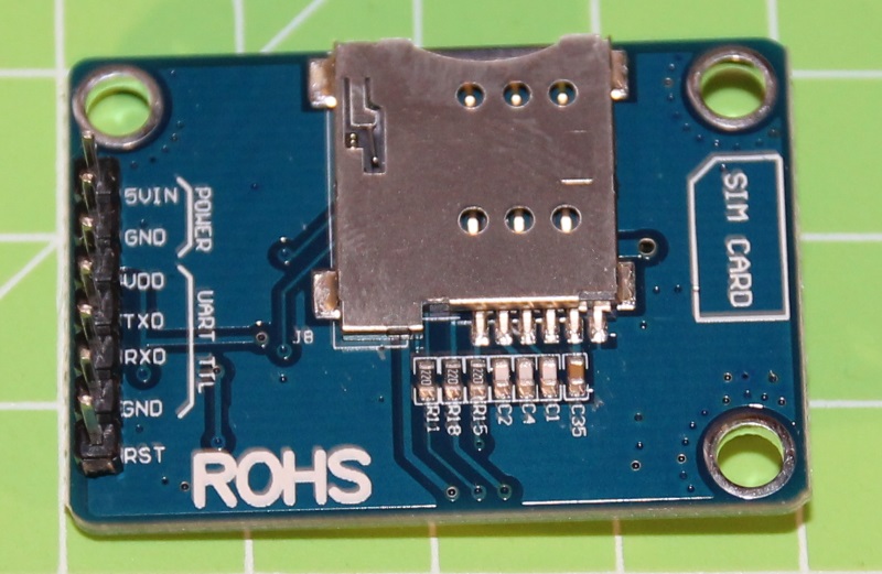
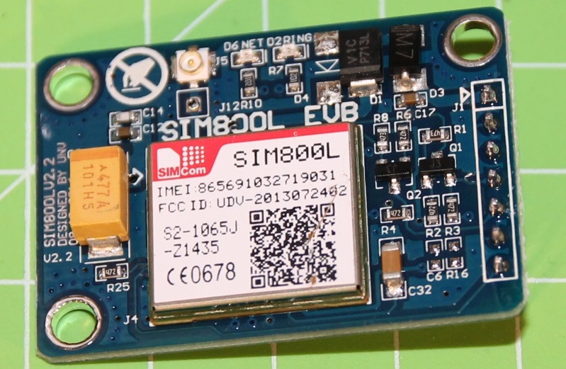
The small module (about 3x4cm) has the SIM800 chip and most of the components on one side, while on the other side you can find the sim card connector:
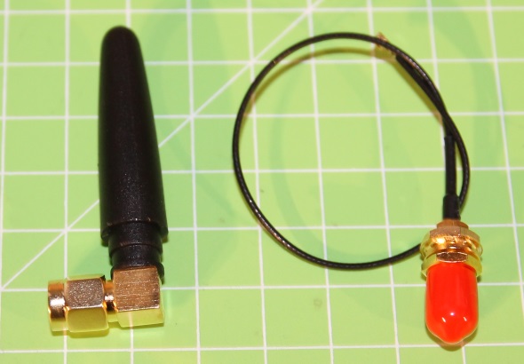
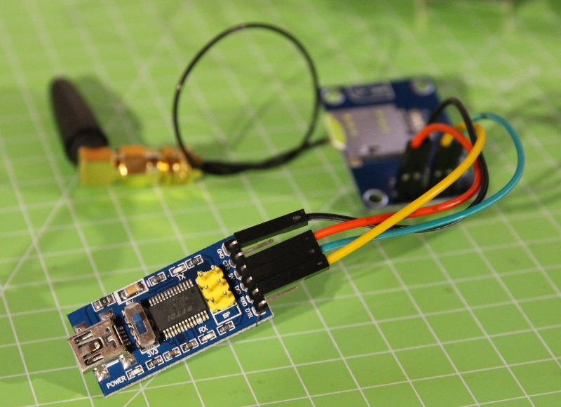
I chose to buy the module with an external antenna… in addition to the module you therefore receive the antenna and a short (about 20cm) cable to connect it:
The module is powered with 5V, offers a serial interface and you can control it using AT commands.

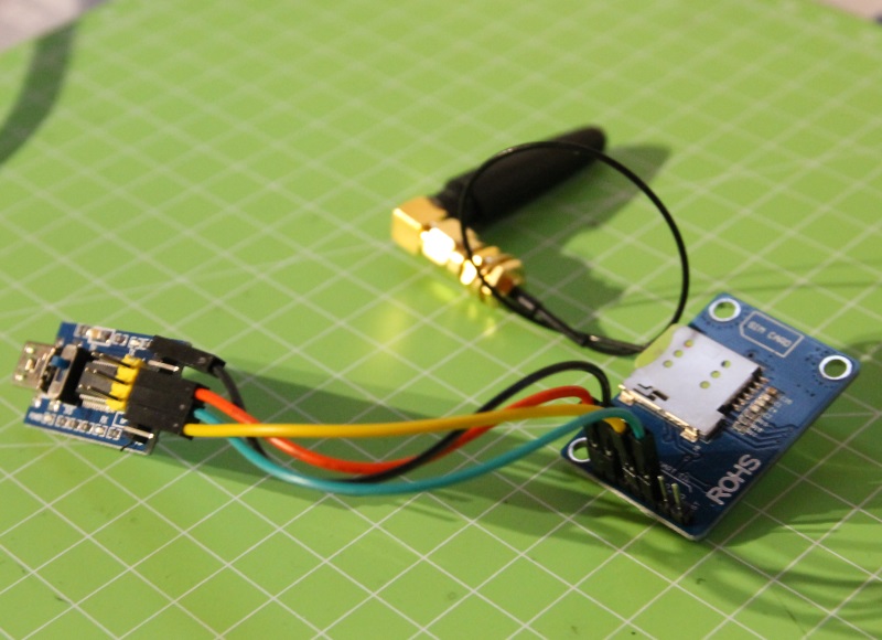
To verify if the module works you can therefore connect it to your PC using a simple USB – serial converter and send the correct AT commands as the manual explains. Be careful to invert the TX and RX pins: the TX pin of your adapter must be connected to the RX pin of the GSM module and viceversa:
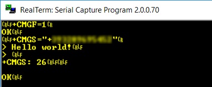
The simplest test is to send and receive an SMS. For simplicity first configure the text mode (=1) with the command AT+CMGF=1. The module will answer with the command you send (without the starting AT) followed by OK.
Now you can specify the recipient of the message with the command AT+CMGS=”number“. After having sent the “carriage return” character, the module will send the > prompt, after which you can type the text of the message. End the message with the character 0x1A (CTRL-Z); the module will answer with the command you sent followed by the number of characters in the message (26):
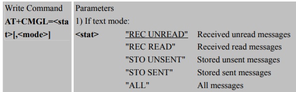
When a new SMS is received, the module sends the +CMTI message. You can read the messages with the AT+CMGL command and you can also specify a filter (for example REC UNREAD, that is all the messages received but not read yet):

The filters available are listed in the manual:
After having verified that the module works, you can now realize a more complex project, for example interfacing it with your Arduino…


Ciao, mi sono imbattuto nel tuo sito cercando informazioni sul modulo sim800c che non riesco a far funzionare! Ti volevo chiedere: tu fai riferimento ad una alimentazione di 2amp che necessariamente arriva sui pin vcc e gnd dal modulino usb-ttl; i miei problemi potrebbero derivare dal fatto che questi 2amp probabilmente non arrivano? Grazie
ciao! il modulo richiede molta corrente quindi deve essere alimentato esternamente, non puoi usare i 5V che arrivano dal convertitore USB->seriale.
sim 800l
salve è possibile inserire nello sketch solo numeri diciamo autorizzati, in modo che altri numeri di cellulare non possono compiere nessuna azione grazie
ciao Paolo, sicuramente sì… nel tuo sketch puoi verificare se il numero di telefono che ti ha inviato – ad esempio – l’SMS è “autorizzato”
ciao è possibile alimentare sia arduino che la sim 800l con un’unico alimentatore, se si in che modo ,grazie in anticipo
ciao Paolo, assolutamente sì… prendi un alimentatore da 5V e almeno 2A e collega Arduino e il modulo SIM800 in parallelo.
ciao, è possibile realizzare un access point con questo modulo e raspberry pi 3?
ciao! per fare un access point ti basta il raspberry… vedi ad esempio questa guida.
Ciao, utilizzo un SIM800C che purtroppo spesso non riesce a comunicare con la SIM, ho provato a misurare la tensione sulla slot SIM e spesso è a zero. il modulo quindi non si connette a nessuna rete e nemmneo riesce a leggere il CCID della SIM. Cosa può essere successo?
ciao, probabilmente l’alimentazione che fornisci al modulo non è sufficiente… anche a me è capitato: verifica che il tuo alimentatore possa garantire almeno 2A.
Salve Luca,
volevo chiederti un’ informazione.
La scheda SIM che hai utilizzato in questo progetto è una normale 4G o una GSM GPRS?
Io ho acquistato questo modulo https://www.amazon.it/dp/B07B2V27VF/ref=pe_3310731_189395851_TE_3p_dp_1 per connetterlo con un raspberry pi 3 con scheda SIM dati della Vodafone 4g, ma non riesco in alcun modo a farli dialogare. Ti ringrazio anticipatamente per una tua eventuale risposta.
ciao, è una normalissima SIM vodafone… non l’ho però mai provato con Raspberry ma “solo” con microcontrollori quali Arduino.
Ti ringrazio tantissimo per la celere risposta.
Credo a questo punto ci sia qualcosa nei vari collegamenti…
Se non ti disturbo magari + avanti ti ricontatto.
Grazie ancora.
nessun problema!
Ciao Luca,
ho lo stesso modulo ma non riesco a comunicare con la seriale del PC.
Il modulo (lato GSM) sembra che funzioni, i lampeggi sono giusti e se gli mando un SMS o telefono le casse del PC “impazziscono”.
La linea risulta libera, il numero è raggiungibile.
Lo alimento con un alimentatore esterno da 3A, lato PC ho provato 2 adattatori USB, uno con il CP102 e l’altro con FTDI ma non mi risponde.
Uno dei due è a 3.3V, l’altro (credo) TTL, può essere questo ? Ho collegato RX e TX invertiti e il GND all’altro GND disponibile per avere il riferimento comune di massa.
Tu, se non sono indiscreto cosa hai usato ?
Ciao Davide! Io ho utilizzato un adattatore FTDI… i tuoi collegamento mi sembrano corretti, sulla seriale non ti appare nulla? Non riesci proprio ad inviare comandi? A breve pubblicherò un progettino con questo modulo, magari seguendo il mio tutorial riuscirai a risolvere